- 4.9/5.0
- 106 Questions
- Updated on: 25-May-2026
- Enterprise Routing and Switching Specialist (JNCIS-ENT)
- 1106+ Prepared
- Valid Worldwide
Free JN0-351 Practice Test Questions | Know You're Ready for Enterprise Routing and Switching Specialist (JNCIS-ENT)
This isn't guesswork. It's a mirror of the real Enterprise Routing and Switching Specialist (JNCIS-ENT) exam. Our free JN0-351 practice test questions reveals exactly what you know, what you don't, and what you need to drill before exam day. No surprises. No outdated Enterprise Routing and Switching Specialist (JNCIS-ENT) exam questions. Just a clear path to your Juniper certification.
What are two purposes of an aggregate route? (Choose two.)
A. to decrease the number of route advertisements
B. to hide internal routes from external peers
C. to allow external peers to see internal routes
D. to increase the number of route advertisements
B. to hide internal routes from external peers
Explanation:
An aggregate route combines multiple specific routes into one less‑specific prefix (e.g., summarizing 10.1.1.0/24, 10.1.2.0/24, and 10.1.3.0/24 into 10.1.0.0/22). This directly achieves two primary goals.
A. To decrease the number of route advertisements.
By advertising a single aggregate prefix instead of many specific routes, you reduce the routing table size and update frequency, conserving router memory, CPU, and bandwidth. This is a fundamental scaling technique in large networks.
B. To hide internal routes from external peers.
When you advertise only the aggregate to external neighbors (e.g., BGP peers), the specific internal subnets remain unknown outside your autonomous system. This improves security and stability because internal route flaps or changes do not propagate to external routers.
Why the other options are wrong:
C. To allow external peers to see internal routes.
Incorrect. Aggregation does the opposite—it prevents external peers from seeing specific internal routes. If you wanted external peers to see internal routes, you would advertise them individually, not aggregate them.
D. To increase the number of route advertisements.
Incorrect. Aggregation reduces the number of advertisements, not increases it. Increasing advertisements would harm network performance and is never a purpose of aggregation.
References:
Juniper Networks TechLibrary:“Understanding Aggregate Routes” – states that aggregate routes “reduce the number of routes in the routing table and limit the propagation of specific prefixes to neighbors.”
Your GRE tunnel is not transitioning to the Up status. What would be the first step in troubleshooting the problem?
A. Verify tunnel endpoint reachability.
B. Verify that the status of the management interface is up.
C. Verify the status of the management routing instance.
D. Verify that the routing instance for GRE tunnels is created.
Explanation:
For a GRE tunnel to transition to the Up state, the tunnel endpoints must be able to communicate with each other at the IP level. The tunnel source and destination addresses are used to encapsulate packets, and if the destination is unreachable (no route in the appropriate routing table), GRE keepalives (if configured) will fail or the interface will remain down. Therefore, the logical first step is to verify endpoint reachability, typically by pinging the destination IP from the source router. Without basic IP connectivity between endpoints, the GRE tunnel cannot come up.
Why other options are wrong:
B. Verify that the status of the management interface is up.
Incorrect. The management interface (e.g., fxp0 or em0) is used for out‑of‑band management and is not involved in forwarding GRE tunnel traffic. GRE tunnels rely on forwarding interfaces or routing instances, not the management interface.
C. Verify the status of the management routing instance.
Incorrect. The management routing instance is reserved for management traffic only. GRE tunnels operate within the default routing instance or a user‑defined non‑management routing instance. Checking the management instance is irrelevant.
D. Verify that the routing instance for GRE tunnels is created.
Incorrect. While GRE tunnels can reside in a non‑default routing instance, this is not required; they can also be in the default instance. Moreover, this is a configuration check, not the first troubleshooting step. Layer 3 reachability must be confirmed before investigating routing instance configuration.
Reference:
Juniper TechLibrary: “Troubleshoot GRE Tunnels” – “First, ensure that the tunnel destination address is reachable from the source router.”
JNCIS‑ENT Study Guide (Tunnels chapter) – “Basic IP connectivity between tunnel endpoints is a prerequisite for GRE tunnel state Up.”
You have two OSPF routers forming an adjacency. R1 has a priority of 32 and a router ID of 192.168.1.2. R2 has a priority of 64 and a router ID of 192.168.1.1. The routers were started at the same time and all other OSPF settings are the default settings. Which statement is correct in this scenario?
A. At least three routers are required for a DR/BDR election.
B. Router IDs must match for an adjacency to form.
C. R2 will be the BDR.
D. R1 will be the BDR.
Explanation:
In an OSPF broadcast network (e.g., Ethernet), the router with the highest interface priority becomes the Designated Router (DR), and the router with the second‑highest priority becomes the Backup Designated Router (BDR). If priorities are equal, the highest router ID (RID) breaks the tie. Here, R1 has priority 32, R2 has priority 64. R2 has the higher priority, so R2 becomes the DR. R1, with the next highest priority, becomes the BDR. Therefore, R1 will be the BDR is correct.
Why other options are wrong:
A. At least three routers are required for a DR/BDR election. Incorrect. Two routers are sufficient for a DR/BDR election. One becomes DR, the other BDR. A third router would become a DROther.
B. Router IDs must match for an adjacency to form. Incorrect. Router IDs must be unique within an OSPF domain. If they matched, adjacency would fail due to duplicate RID detection.
C. R2 will be the BDR. Incorrect. R2 has the higher priority (64 vs. 32), so R2 becomes the DR, not the BDR.
Additional note:
Because both routers started at the same time, no pre‑existing DR/BDR roles influence the election; they follow the standard priority‑based selection process. The router ID (192.168.1.1 for R2, 192.168.1.2 for R1) is irrelevant here because priorities are already different.
Reference:
Juniper TechLibrary: “OSPF Designated Router Election” – “The router with the highest priority on a network segment becomes the DR; the router with the second‑highest priority becomes the BDR.”
JNCIS‑ENT Study Guide (OSPF chapter) – “On broadcast multi‑access networks, DR/BDR election uses priority first, then router ID as tie‑breaker.”
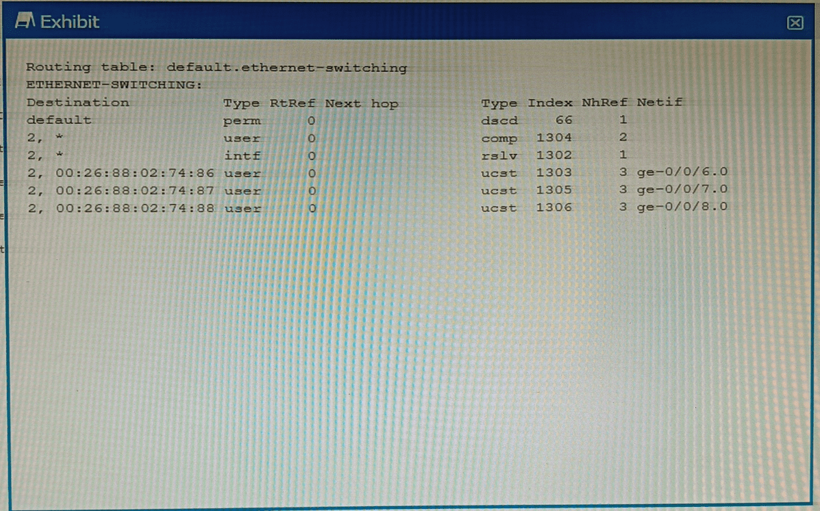
Exhibit

Which command displays the output shown in the exhibit?
A. show route forwarding-table
B. show ethernet-switching table
C. show ethernet—switching table extensive
D. show route forwarding—table family ethernet-switching
Explanation:
The exhibit displays a routing table under the heading default.ethernet-switching. This table contains entries such as a default route (next hop dscd, meaning discard), a 2,* prefix, and specific MAC addresses (00:26:88:02:74:86, etc.) mapped to unicast next hops (ucst) on interfaces ge-0/0/6.0, ge-0/0/7.0, and ge-0/0/8.0. Columns include Destination, Type (perm, user, intf), RtRef, Index, NhRef, and Netif. This output is not the standard MAC address table; instead, it is the forwarding table (PFE view) for the Ethernet switching family. On Juniper devices, the command show route forwarding-table family ethernet-switching displays exactly this information, showing how Layer 2 frames are forwarded through the system, including next‑hop types, discard routes, and interface associations. The presence of dscd (discard) for the default entry and ucst (unicast) for MAC‑based entries confirms this is a forwarding table, not a learning table.
Why other options are wrong:
A. show route forwarding-table
– Without the family ethernet-switching option, this command defaults to showing IPv4 (inet) forwarding entries. The exhibit contains no IPv4 addresses; it shows MAC addresses and ethernet‑switching‑specific next‑hop types. Therefore, this command would produce a completely different output (e.g., inet table with intf/unicast entries for IP prefixes).
B. show ethernet-switching table
– This displays the Layer 2 MAC learning table (also called the bridge table). Its typical output includes columns like VLAN, MAC address, Type, Age, and Interface. It does not show perm, dscd, ucst, RtRef, Index, or NhRef, nor does it present data in a routing‑table format. The exhibit lacks VLAN and Age fields, so this cannot be the correct command.
C. show ethernet-switching table extensive
– This adds even more detail to the MAC table, such as Flags, Last seen, and Learned from. The exhibit has none of these fields. Extensive output still does not resemble the routing‑table style shown. Like option B, it is for the bridge learning database, not the forwarding table.
References:
Juniper TechLibrary: “show route forwarding-table family ethernet-switching” – “Displays the Ethernet switching forwarding table, including discard routes, unicast next hops, and interface indices.”
JNCIS‑ENT Study Guide (Layer 2 Bridging and Forwarding) – “Use show route forwarding-table family ethernet-switching to examine the PFE’s forwarding entries for Layer 2 traffic.”
Which two statements are true about the default VLAN on Juniper switches? (Choose two.)
A. The default VLAN is set to a VLAN ID of 1 by default
B. The default VLAN ID is not assigned to any interface.
C. The default VLAN ID is not visible.
D. The default VLAN ID can be changed.
Explanation:
A. The default VLAN is set to a VLAN ID of 1 by default.
This is correct. On Juniper EX series switches, the default VLAN (named default) is preconfigured with VLAN ID 1. All switch ports initially belong to this VLAN as untagged members unless changed. VLAN 1 is the traditional default VLAN in many vendor switches, including Juniper.
D. The default VLAN ID can be changed.
This is also correct. Although the default VLAN initially uses VLAN ID 1, an administrator can modify it. For security or operational reasons, you may want to change the default VLAN ID to a different number (e.g., set vlans default vlan-id 999). After changing the ID, the VLAN still acts as the default VLAN for ports that remain in it, but traffic now uses the new VLAN ID.
Why B and C are incorrect:
B. The default VLAN ID is not assigned to any interface.
Incorrect. On a fresh Juniper switch, all interfaces belong to the default VLAN (VLAN ID 1) as untagged members. In fact, the default VLAN initially includes every access port. This is the opposite of "not assigned to any interface."
C. The default VLAN ID is not visible.
Incorrect. The default VLAN and its VLAN ID are fully visible in the configuration and operational commands. You can see the default VLAN by running show vlans or show configuration vlans. If it were not visible, troubleshooting and management would be nearly impossible. For example, the output of show vlans clearly displays default with VLAN ID 1. The statement might be confused with the default VLAN on some other platforms being "hidden," but that is not true for Juniper.
References:
Juniper TechLibrary: "Understanding VLANs on EX Series Switches" – "The default VLAN, named default, is assigned VLAN ID 1 and contains all interfaces initially."
Juniper TechLibrary: "Changing the Default VLAN ID" – "You can change the VLAN ID of the default VLAN using the vlan-id statement under the vlans default hierarchy."
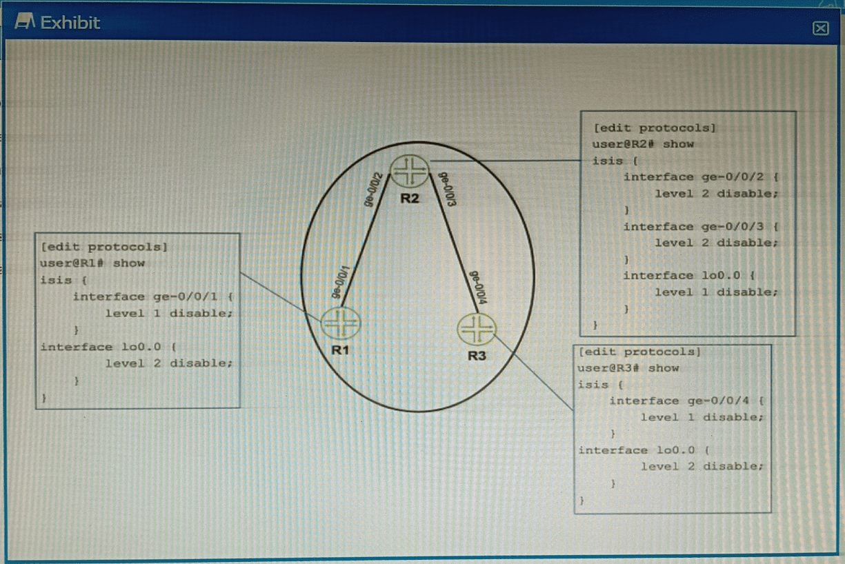
Exhibit

Referring to the exhibit, which two configuration changes must you apply for packets to
reach from R1 to R3 using IS-IS? (Choose two.)
A. On R1, enable Level 1 on the ge-0/0/1 interface.
B. On R3 disable Level 2 on the ge-0/0/4 interface.
C. On R1, disable Level 2 on the ge-0/0/1 interface.
D. On R3 enable Level 1 on the ge-0/0/4 interface
Explanation:
The exhibit shows IS-IS configurations on R1 and R3. IS-IS supports two levels:
Level 1 (intra-area routing, similar to OSPF non-backbone)
Level 2 (inter-area routing, similar to OSPF backbone)
For two routers to form an adjacency and exchange routes, they must share at least one common IS-IS level on the connecting interface.
A. On R1, enable Level 1 on the ge-0/0/1 interface.
Currently, R1’s ge-0/0/1 is not shown, so it presumably has defaults. Enabling Level 1 gives a common level with R3’s ge-0/0/4 once Level 1 is also enabled there.
D. On R3, enable Level 1 on the ge-0/0/4 interface.
R3’s ge-0/0/4 currently has Level 1 disabled. Removing level 1 disable allows Level 1 adjacencies.
Why B and C are incorrect:
B. On R3 disable Level 2 on ge-0/0/4
– This would leave Level 2 still disabled? Actually, it already has Level 1 disabled, so only Level 2 is active. Disabling Level 2 would leave no levels active on that interface, breaking adjacency.
C. On R1 disable Level 2 on ge-0/0/1
– Disabling Level 2 does not help because R3’s interface currently requires Level 2 (only Level 2 is active). Disabling Level 2 on R1 would remove the only possible common level.
Reference:
Juniper TechLibrary:“IS-IS Levels and Adjacencies” – “Neighbors must share at least one enabled level (Level 1 or Level 2) on the connecting interface to form an adjacency.”
JNCIS-ENT Study Guide (IS-IS chapter) – “Level 1 routers route within an area; Level 2 routes between areas. Mismatched levels prevent adjacency formation.”
What is a purpose of using a spanning tree protocol?
A. to look up MAC addresses
B. to eliminate broadcast storms
C. to route IP packets
D. to tunnel Ethernet frames
Explanation:
A spanning tree protocol (STP, RSTP, MSTP) is used in Ethernet networks to prevent Layer 2 loops. Loops occur when there are redundant paths between switches, causing broadcast frames to circulate endlessly. This leads to broadcast storms, which consume bandwidth, overload switch CPUs, and can bring down the network. STP logically disables redundant links by placing them in a blocking state, allowing only a single active path between any two switches. If the active path fails, STP re‑converges and unblocks a previously blocked port. By eliminating loops, STP directly eliminates broadcast storms.
Why other options are wrong:
A. To look up MAC addresses.
Incorrect. MAC address lookup is performed by the switch’s forwarding logic using the MAC address table (learned from source addresses). STP does not participate in MAC learning or lookup; it only manages loop prevention.
C. To route IP packets.
Incorrect. Routing IP packets is a Layer 3 function performed by routers or Layer 3 switches using routing tables. STP operates at Layer 2 and has no knowledge of IP addresses or routing.
D. To tunnel Ethernet frames.
Incorrect. Tunneling Ethernet frames (e.g., over GRE, L2TP, or MPLS) is used to transport Layer 2 traffic across a Layer 3 network. STP does not provide tunneling; it is strictly a loop‑avoidance mechanism within a switched network.
Reference:
IEEE 802.1D (STP standard) – “The Spanning Tree Protocol eliminates loops from a bridged network, preventing broadcast radiation and instability.”
Juniper TechLibrary: “Understanding Spanning Tree Protocols” – “The primary purpose of STP is to maintain a loop‑free Layer 2 topology and prevent broadcast storms.”
You are asked to change the setting for the LSAs age out back to the default value. In this scenario, which time interval will accomplish this task?
A. 1800 seconds
B. 600 seconds
C. 300 seconds
D. 3600 seconds
Explanation:
In OSPF, every Link State Advertisement (LSA) has an age field. The default maximum age (MaxAge) for an LSA is 3600 seconds (1 hour). When an LSA reaches this age without being refreshed by its originating router, it is considered invalid and is automatically removed (aged out) from the Link State Database (LSDB).
To prevent LSAs from reaching this maximum age, the originating router periodically refreshes its LSAs every 1800 seconds (30 minutes). This refresh action resets the age of the LSA to zero, ensuring that valid LSAs never reach the 3600-second expiration threshold under normal operating conditions.
To answer the specific question: If a network administrator has previously changed the LSA aging setting and is now asked to revert it to the default value, they must restore the MaxAge parameter to 3600 seconds. This ensures LSAs will time out and be removed from the database after one hour if no refresh is received.
Why the other options are incorrect:
A. 1800 seconds:
This is the LSRefreshTime, which controls how often a router sends out refreshed copies of its LSAs to prevent them from aging out. This is a different timer and not the age-out value.
B. 600 seconds:
his value (10 minutes) does not correspond to any standard LSA timer and is not the default aging interval.
C. 300 seconds:
Similarly, this value (5 minutes) is not the default LSA MaxAge or Refresh timer. While OSPF uses 300 seconds (5 minutes) for the "dead interval" for neighbor adjacency, it is not applicable to LSA aging.
Reference:
Juniper Networks Technical Documentation: OSPF LSAs have a maximum age of 3600 seconds (1 hour). When an LSA reaches this age, it is considered invalid and is removed from the OSPF database.
OSPF RFC (Request for Comments):
The MaxAge is defined as an architectural constant of 3600 seconds.
| Page 1 out of 14 Pages |
Why Take This JN0-351 Enterprise Routing and Switching Specialist (JNCIS-ENT) Practice Exam Before the Real Exam?
This free Enterprise Routing and Switching Specialist (JNCIS-ENT) practice test gives you three critical advantages:
- Real format, real pressure – Identical question structure and difficulty to the official exam
- Instant gap detection – You'll know exactly which topics need more attention
- Learn as you go – Every answer includes a clear explanation, so you're studying while testing