• 4.9/5.0
  • 106 Questions
  • Updated on: 12-Jun-2026
  • Enterprise Routing and Switching Specialist (JNCIS-ENT)
  • 1106+ Prepared
  • Valid Worldwide

Free JN0-351 Practice Test Questions | Know You're Ready for Enterprise Routing and Switching Specialist (JNCIS-ENT)


Your network has two ISPs available. You want to ensure that all outbound traffic is routed out ISP-1. If the connection to ISP-1 fails, all outbound traffic is routed to the backup ISP ISP-2. In this scenario, how should you configure BGP on your network?

A. Set the local-preference attribute to a higher value tor ISP-2 than ISP-1.

B. Set the local-preference attribute to a higher value for ISP-1 than ISP-2.

C. Configure the gateway for ISP-1 with a higher peer ID than the gateway for ISP-2.

D. Configure the gateway for ISP-1 with a higher origin code than the gateway for ISP-2.

B.   Set the local-preference attribute to a higher value for ISP-1 than ISP-2.

Explanation:

Local preference (local-pref) is a BGP attribute used within an autonomous system (AS) to select an outbound path for traffic leaving the AS. The higher the local preference value, the more preferred the route.

Why other options are wrong

A. Set the local-preference attribute to a higher value for ISP-2 than ISP-1.
Incorrect. This would make ISP-2 the preferred path for outbound traffic, which is the opposite of the requirement.

C. Configure the gateway for ISP-1 with a higher peer ID than the gateway for ISP-2.
Incorrect. The peer ID (router ID) is used for BGP neighbor identification and tie‑breaking in the BGP path selection algorithm, but it is compared after local preference, AS path length, origin, MED, and other attributes. It cannot override local preference. Also, a higher peer ID does not mean higher preference; BGP prefers the lower router ID when all earlier attributes are equal.

D. Configure the gateway for ISP-1 with a higher origin code than the gateway for ISP-2.
Incorrect. Origin code is an attribute indicating how the route was injected into BGP (IGP > EGP > incomplete). A higher origin code is less preferred (e.g., incomplete is least preferred). More importantly, origin code is compared after local preference and AS path length, so it is not the correct primary mechanism for this redundancy design.

Reference

Juniper TechLibrary: “BGP Local Preference” – “Local preference is used to influence outbound traffic selection within an AS. The route with the highest local preference value is preferred for traffic leaving the AS.”

JNCIS‑ENT Study Guide (BGP Attributes) – “Local preference is the most common attribute used to select a primary ISP link. Higher values are more preferred. Backup links receive default or lower values.”

What does the MAC limiting feature do on EX Series switches?

A. It limits the number of MAC addresses learned on an access port.

B. It limits the number of MAC addresses learned on a trunk port.

C. It limits the acceptable values for a MAC address to a specified range.

D. It limits the time a learned MAC address stays in the MAC routing table.

A.   It limits the number of MAC addresses learned on an access port.

Explanation:

The MAC limiting feature on Juniper EX Series switches protects against flooding of the Ethernet switching table (MAC forwarding table) by limiting the number of MAC addresses that can be learned on a single Layer 2 access interface . This prevents two common network attacks:

DHCP starvation attacks – An attacker floods the network with DHCP requests using spoofed MAC addresses, exhausting the DHCP server's resources

Ethernet switching table overflow attacks – An attacker fills the switch's MAC table, forcing the switch to broadcast all messages

When you configure a MAC limit, you specify the maximum number of dynamic MAC addresses allowed per interface. Once the limit is exceeded, the switch takes a configured action such as dropping packets with new MAC addresses, generating a system log entry, or shutting down the interface .

Why Other Options Are Wrong

B. It limits the number of MAC addresses learned on a trunk port.
– Incorrect. While MAC limiting itself can be applied to trunk ports on EX Series switches, the question asks for the purpose/description of the feature. Additionally, trunk ports are automatically trusted by default for port security features . The official documentation explicitly states MAC limiting protects against flooding on "a single Layer 2 access interface" .

C. It limits the acceptable values for a MAC address to a specified range.
– Incorrect. MAC limiting sets a quantity restriction (number of addresses), not a value range restriction. Juniper does offer a separate feature called "allowed MAC addresses" that restricts learning to specific MAC values, but this is distinct from MAC limiting .

D. It limits the time a learned MAC address stays in the MAC routing table.
– Incorrect. This describes the MAC aging timeout feature, which controls how long learned MAC entries remain in the table before being removed (default 60 seconds) . MAC limiting is about quantity, not duration.

Reference

Juniper Networks Documentation: "Understanding MAC Limiting and MAC Move Limiting for Port Security on EX Series Switches" – "MAC limiting sets a limit on the number of MAC addresses that can be learned on a single Layer 2 access interface or on all the Layer 2 access interfaces on the switch"

Juniper Networks Documentation: "Example: Configuring MAC Limiting" – Protects against DHCP starvation and Ethernet switching table overflow attacks

Which statement is correct about controlling the routes installed by a RIB group?

A. An import policy is applied to the RIB group.

B. Only routes in the last table are installed.

C. A firewall filter must be configured to install routes in the RIB groups.

D. An export policy is applied to the RIB group.

A.   An import policy is applied to the RIB group.

Explanation:

A Routing Information Base (RIB) group allows you to share routes between different routing tables (e.g., copying routes from inet.0 to a VRF table or vice versa). When you use a RIB group to import routes from one routing table into another, you need granular control over which specific routes are actually installed in the destination table.

This control is achieved by applying an import policy to the RIB group. The import-policy statement is configured under the [edit routing-options rib-groups] hierarchy and references a policy that filters or modifies routes before they are placed into the new table. Without this policy, the RIB group copies routes based purely on the import-rib statement; with the policy applied, the switch only installs routes that match the policy's criteria.

Why other options are wrong

B. Only routes in the last table are installed.
Incorrect. The import-rib statement lists one or more routing tables. The first table listed is the primary table, and routes are installed into all tables specified in the list, not just the last one.

C. A firewall filter must be configured to install routes in the RIB groups.
Incorrect. Firewall filters operate on traffic forwarding (data plane), not on routing table imports (control plane). Controlling routes installed by a RIB group is done with routing policies, not firewall filters.

D. An export policy is applied to the RIB group.
Incorrect. An export-policy (or export-rib statement) is used when a protocol advertises routes to neighbors, while import-policy controls which routes are received and installed into the local routing table. For RIB groups specifically, import-policy is the correct statement to filter routes being copied between tables.

Reference

Juniper Networks Documentation: "import-policy" – "Apply one or more policies to routes imported into the routing table group"

Juniper Networks Documentation: "rib-groups" – "After specifying the routing table from which to import routes, you can apply one or more policies to control which routes are installed... include the import-policy statement"

Exhibit:

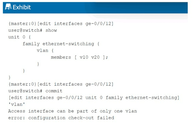
When trying to commit the configuration shown in the exhibit, you receive an error. What is the problem?

A. You have omitted the interface-mode trunk command.

B. You have not configured an IP address to the interface.

C. You have not set the interface family correctly.

D. You have omitted the interface-mode access command.

A.   You have omitted the interface-mode trunk command.

Explanation:

The error message states: "Access interface can be part of only one vlan". This indicates that the switch is treating ge-0/0/12 as an access port by default. Access ports allow membership in only a single VLAN.

However, the configuration attempts to assign the interface to two VLANs (v10 and v20) using the members [ v10 v20 ]; statement. This is only possible on a trunk port, which can carry multiple VLANs (tagged).

Because the interface-mode trunk command is missing, the switch defaults to access mode, causing the commit to fail. Adding interface-mode trunk; under the vlan hierarchy resolves the issue.

Why other options are wrong

B. You have not configured an IP address to the interface.
Incorrect. This is a Layer 2 switching interface (family ethernet-switching). IP addresses are not required or typically configured on such interfaces. Layer 3 functions are handled by VLAN interfaces (IRB/vlan unit), not physical access/trunk ports.

C. You have not set the interface family correctly.
Incorrect. The family ethernet-switching is correct for a switch port. Changing the family to inet would convert it to a Layer 3 interface, which would not solve the multi‑VLAN membership issue.

D. You have omitted the interface-mode access command.
Incorrect. Access mode is the default; omitting interface-mode access does not cause an error because it is implicit. Adding interface-mode access explicitly would still not allow multiple VLANs — the error would persist because access ports cannot have multiple VLAN members.

Reference

Juniper TechLibrary: “Configuring Trunk Ports” – “For trunk ports, include the interface-mode trunk statement. Trunk ports can carry multiple VLANs. Access ports (default) can belong to only one VLAN.”

JNCIS‑ENT Study Guide (Layer 2 Switching / VLANs) – “Access ports are assigned to a single VLAN. Trunk ports carry multiple VLANs using 802.1Q tagging. Omission of interface-mode trunk when multiple VLANs are listed causes a commit error.”

Exhibit.

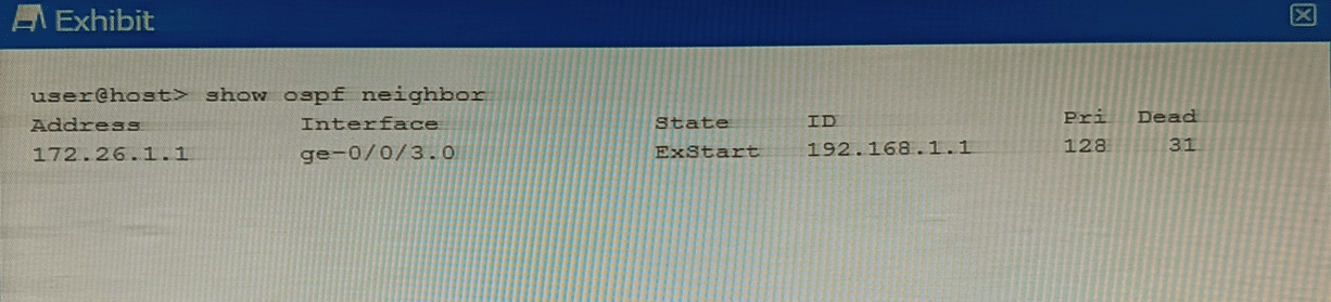
Why is this OSPF adjacency remaining in this state?

A. A subnet mask mismatch exists between the OSPF neighbors.

B. An MTU mismatch exists between the OSPF neighbors.

C. A hello interval mismatch exists between the OSPF neighbors.

D. An area ID mismatch exists between the OSPF neighbors

B.   An MTU mismatch exists between the OSPF neighbors.

Explanation:

The OSPF adjacency is stuck in the ExStart state. In the OSPF neighbor formation process, routers transition through several states: Down → Init → 2-Way → ExStart → Exchange → Loading → Full .

After establishing bidirectional communication (2-Way state), routers enter the ExStart state . During this phase, neighboring routers negotiate a master/slave relationship and determine the initial Database Descriptor (DBD) packet sequence number. The first DBD packet exchanged contains the interface MTU value in the packet header .

❌ Why Other Options Are Wrong

A. A subnet mask mismatch exists between the OSPF neighbors.
Incorrect. Subnet mask mismatches prevent OSPF from advancing beyond the Init or 2-Way state. Hello packets contain subnet mask information, and mismatches cause the adjacency to stall much earlier .

C. A hello interval mismatch exists between the OSPF neighbors.
Incorrect. Hello interval mismatches are detected when Hello packets are first exchanged. This prevents the adjacency from progressing beyond the Init state, not the ExStart state .

D. An area ID mismatch exists between the OSPF neighbors.
Incorrect. Area ID mismatches also cause failure in the Init state. Routers with mismatched area IDs never proceed to neighbor state beyond Init because Hello packets carry the area information, which is validated before any adjacency formation begins .

📚 Reference

Cisco Support Documentation: "Troubleshoot OSPF Neighbors Stuck in Exstart/Exchange State" – "The problem occurs when the maximum transmission unit (MTU) settings for neighboring router interfaces do not match"

ExamTopics JN0-363 Discussion – Community verified answer: "mismatched MTU settings on the OSPF interfaces" is correct

In RSTP, which three port roles are associated with the discarding state? (Choose three.)

A. root

B. backup

C. alternate

D. disabled

E. designated

B.   backup
C.   alternate
D.   disabled

Explanation:

In RSTP (Rapid Spanning Tree Protocol, IEEE 802.1w), port states (Discarding, Learning, Forwarding) are separate from port roles (Root, Designated, Alternate, Backup, Disabled). The Discarding state means the port does not forward traffic and does not learn MAC addresses. It combines the legacy STP states of Blocking, Listening, and Disabled.

Three port roles are associated with the Discarding state in a stable topology:

B. Backup
– A backup port occurs when two ports on the same switch are connected to the same shared LAN segment (e.g., through a hub). One is the Designated port (Forwarding); the other is placed in Discarding as a backup. This role prevents loops on multi-access segments.

C. Alternate
– An alternate port provides a secondary path to the root bridge. It acts as a backup for the root port. In normal operation, it stays in Discarding and transitions to Forwarding only if the current root port fails.

D. Disabled
– A disabled port is administratively shut down (e.g., disable command) or has failed link integrity. It does not participate in RSTP at all and remains permanently in the Discarding state.

Why other options are wrong:

A. Root
– Incorrect. The root port is the switch's best path to the root bridge. In a stable topology, the root port is always in the Forwarding state, never Discarding.

E. Designated
– Incorrect. The designated port forwards traffic toward the root bridge on each LAN segment. Under stable conditions, designated ports are also in the Forwarding state, not Discarding.

References:

Juniper TechLibrary:“Understanding RSTP Port Roles and States” – “Alternate, backup, and disabled ports operate in the discarding state. Root and designated ports are forwarding.”

JNCIS‑ENT Study Guide (Spanning Tree Protocol) – “RSTP discarding state combines blocking, listening, and disabled. Alternate, backup, and disabled ports are discarding.”

Click the Exhibit button.

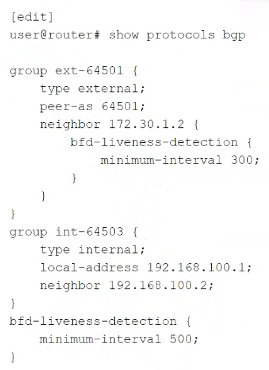
Which statement concerning Bidirectional Forwarding Detection (BFD) is true for the configuration shown in the exhibit?

A. The effective interval for neighbor 172.30.1.2 is 500 ms.

B. The effective interval for neighbor 192.168.100.2 is 500 ms.

C. The link 1o neighbor 192.168.100.2 is not using BFD.

D. The minimum-interval must match on both ends.

D.   The minimum-interval must match on both ends.

Explanation:

BFD requires both endpoints to agree on detection timing. The configured minimum-interval value on one router must be compatible with the remote router's configuration. If the values are mismatched, the session may fail to establish or may flap. Even if negotiation occurs (using the larger of the two values), the fundamental requirement is that both ends must be configured in a compatible way. Statement D is a universal truth for BFD, independent of the specific numbers in the exhibit.

Why other options are wrong:

A. The effective interval for neighbor 172.30.1.2 is 500 ms.
Incorrect. Neighbor 172.30.1.2 has an explicit BFD configuration with minimum-interval 300 under the neighbor stanza. This overrides the global value (500 ms). The effective interval is 300 ms, not 500 ms.

B. The effective interval for neighbor 192.168.100.2 is 500 ms.
Incorrect in principle, though numerically it might appear true. Neighbor 192.168.100.2 has no explicit BFD configuration, and its group (int-64503) also has none, so it inherits the global value of 500 ms on the local router. However, the statement implies this is the effective interval for the session. BFD requires both ends to agree; without knowing the remote router's configuration, we cannot confirm the effective session interval. More importantly, many exam resources treat this statement as incorrect because the question focuses on BFD requirements, not just local inheritance. The guaranteed true statement is D.

C. The link to neighbor 192.168.100.2 is not using BFD.
Incorrect. Because the global BFD configuration applies to all BGP peers without their own BFD settings, neighbor 192.168.100.2 is using BFD with the global minimum-interval 500.

References:

Juniper TechLibrary: “BFD Minimum Interval” – “The minimum interval must be compatible on both sides of the BFD session.”

JNCIS‑ENT Study Guide (BFD) – “BFD configuration hierarchy: neighbor overrides group, group overrides global. Mismatched intervals across peers prevent session establishment.”

Which statement about aggregate routes is correct?

A. Aggregate routes can only be used for static routing but not for dynamic routing protocols.

B. Aggregate routes are automatically generated for all of the subnets in a routing table.

C. Aggregate routes are always preferred over more specific routes, even when the specific routes have a better path.

D. Aggregate routes are used for advertising summarized network prefixes.

D.   Aggregate routes are used for advertising summarized network prefixes.

Explanation:

An aggregate route is a user‑defined summary prefix (e.g., 10.0.0.0/8) that combines multiple more‑specific routes into one advertisement. Its primary purpose is to reduce the number of routes advertised to neighboring routers, thereby improving scalability and hiding internal topology details. Aggregate routes do not forward traffic unless they have contributing routes, but they are commonly used to advertise summarized prefixes in routing protocols like OSPF, IS‑IS, and BGP.

Why other options are wrong:

A. Aggregate routes can only be used for static routing but not for dynamic routing protocols.
Incorrect. Aggregate routes are frequently used with dynamic routing protocols. For example, an OSPF Area Border Router (ABR) can advertise an aggregate route into Area 0, or BGP can advertise an aggregate prefix. Static routing is not a requirement.

B. Aggregate routes are automatically generated for all of the subnets in a routing table.
Incorrect. Aggregate routes are manually configured by the network administrator. Juniper does not automatically generate aggregates for all subnets; you must explicitly define them under [edit routing-options aggregate].

C. Aggregate routes are always preferred over more specific routes, even when the specific routes have a better path.
Incorrect. A more specific route (e.g., /24) is always preferred over a less specific aggregate (e.g., /8) for forwarding decisions, regardless of path metrics. This is the "longest prefix match" rule in IP routing. The aggregate is only used if no specific route exists for the destination.

Reference:

Juniper TechLibrary:“Understanding Aggregate Routes” – “Aggregate routes combine multiple prefixes into a single advertisement, reducing routing table size and advertisement count.”

JNCIS‑ENT Study Guide (Routing Policy) – “Aggregate routes are manually configured, used for summarization, and are less preferred than more specific prefixes.”

Page 5 out of 14 Pages