• 4.9/5.0
  • 106 Questions
  • Updated on: 12-Jun-2026
  • Enterprise Routing and Switching Specialist (JNCIS-ENT)
  • 1106+ Prepared
  • Valid Worldwide

Free JN0-351 Practice Test Questions | Know You're Ready for Enterprise Routing and Switching Specialist (JNCIS-ENT)


Which statement is correct about graceful Routing Engine switchover (GRES)?

A. The PFE restarts and the kernel and interface information is lost.

B. GRES has a helper mode and a restarting mode.

C. When combined with NSR, routing is preserved and the new master RE does not restart rpd.

D. With no other high availability features enabled, routing is preserved and the new master RE does not restart rpd.

C.   When combined with NSR, routing is preserved and the new master RE does not restart rpd.

Explanation:

Graceful Routing Engine switchover (GRES) is a Juniper high availability feature that allows a switchover from the master Routing Engine (RE) to the backup RE without interrupting packet forwarding. When GRES is enabled, the Packet Forwarding Engine (PFE) continues to forward traffic during the switchover, and interface information is preserved. However, GRES alone does not preserve routing protocols; control plane protocols (e.g., OSPF, BGP, IS‑IS) restart on the new master RE, and rpd (routing protocol daemon) restarts from scratch. This can cause neighbor resets and temporary routing instability.

Why other options are wrong:

A. The PFE restarts and the kernel and interface information is lost.
Incorrect. During GRES, the PFE does not restart; it continues forwarding traffic. Kernel and interface information are preserved across the switchover. This is the "graceful" aspect of GRES.

B. GRES has a helper mode and a restarting mode.
Incorrect. That description applies to Graceful Restart (GR), not GRES. Graceful Restart has a restarting router and helper routers. GRES is about Routing Engine switchover, not protocol restart helper mechanisms.

D. With no other high availability features enabled, routing is preserved and the new master RE does not restart rpd.
Incorrect. GRES alone does not preserve routing protocols; rpd restarts on the new master RE. Without NSR, protocol adjacencies are lost and must be re‑established. Only when GRES is combined with NSR is rpd preserved.

References:

Juniper TechLibrary: “Understanding Graceful Routing Engine Switchover (GRES)” – “GRES preserves interface and kernel information and keeps the PFE forwarding during switchover, but routing protocols restart unless NSR is also configured.”

Juniper TechLibrary: “Understanding Non‑Stop Routing (NSR)” – “When combined with GRES, NSR ensures the standby RE is fully synchronized so the new master RE does not restart rpd.”

Which two statements are correct about Martian routes? {Choose two.)

A. Martian routes are never installed in the route table.

B. Additional prefixes can be added to the list of Martian routes.

C. Martian routes only represent publicly used prefixes.

D. Martian routes are always host addresses.

A.   Martian routes are never installed in the route table.
B.   Additional prefixes can be added to the list of Martian routes.

Explanation:

A. Martian routes are never installed in the route table.
This is correct. Martian routes are defined as invalid or suspicious IP addresses and prefixes (e.g., loopback addresses, broadcast addresses, multicast ranges, and reserved/unused address spaces). Juniper devices, by default, discard any packet with a source or destination address matching a Martian prefix. These prefixes are explicitly excluded from the routing table and forwarding table. Even if a static route or dynamic routing protocol tries to install such a route, the device will reject it. Martian filters operate as a protection mechanism before route installation.

B. Additional prefixes can be added to the list of Martian routes.
This is also correct. Junos OS allows network administrators to customize the Martian list to suit their security policies. You can add new prefixes to be treated as Martian (discarded) or remove default Martian prefixes if necessary. The configuration is done under the [edit routing-options martians] hierarchy. For example, set routing-options martians 10.0.0.0/8 orlonger would treat all RFC 1918 private addresses as Martian (though this is not typical for private networks). This flexibility is essential for special security or routing policies.

Why C and D are incorrect:

C. Martian routes only represent publicly used prefixes.
Incorrect. Martian routes primarily represent invalid, reserved, or special-purpose addresses, which are often not publicly routable (e.g., 0.0.0.0/8, 127.0.0.0/8, 224.0.0.0/4, 240.0.0.0/4). However, the statement says "only publicly used prefixes" — that is wrong because public prefixes (e.g., 8.8.8.8/32) are not Martian by default. Martians are the opposite of normal public prefixes. Additionally, private addresses (e.g., 10.0.0.0/8) are not default Martians but can be added. So the definition is not about "publicly used."

D. Martian routes are always host addresses.
Incorrect. Martian routes can be host addresses (e.g., 127.0.0.1/32) or entire networks (e.g., 0.0.0.0/8, 255.0.0.0/8). They are defined by prefix and prefix length, often using orlonger to cover subnets as well. Saying they are "always host addresses" is false.

References:

Juniper TechLibrary: “Understanding Martian Addresses” – “Martian addresses are not installed in the routing table or forwarding table; the default list includes reserved and invalid prefixes, and you can add or remove entries.”

JNCIS‑ENT Study Guide (Routing Policy and Filtering) – “Martian routes are discarded and prevented from route table entry; the list is fully configurable.”

You are deploying a trunk port with multiple VLANs. In this scenario, which statement is true about the native VLAN?

A. The native VLAN must be the default VLAN on the port.

B. The native VLAN is automatically configured through DHCP.

C. The native VLAN is an untagged VLAN ID on the port.

D. The native VLAN is the highest tagged VLAN ID on the port.

C.   The native VLAN is an untagged VLAN ID on the port.

Explanation:

On a trunk port, traffic from multiple VLANs is typically carried over the same link using 802.1Q tagging, where each Ethernet frame includes a VLAN tag. However, the native VLAN is an exception: frames belonging to the native VLAN are sent untagged. This allows devices that do not understand 802.1Q tagging (e.g., legacy devices or certain access points) to communicate over the trunk link while still participating in a specific VLAN. On Juniper switches, the native VLAN is defined using the native-vlan-id statement under the trunk interface configuration.

Why other options are wrong:

A. The native VLAN must be the default VLAN on the port.Incorrect. The default VLAN on a Juniper switch is VLAN 1, but the native VLAN can be set to any valid VLAN ID. The two are independent unless explicitly configured that way.

B. The native VLAN is automatically configured through DHCP Incorrect. The native VLAN is a static configuration set on the switch port; it is not learned or assigned dynamically via DHCP.

D. The native VLAN is the highest tagged VLAN ID on the port. Incorrect. The native VLAN is not determined by the highest or lowest tag; it is explicitly configured as a separate parameter. All other VLANs on the trunk are tagged, while the native VLAN is untagged, regardless of VLAN ID number.

Reference:

Juniper TechLibrary: “Configuring Trunk Ports with Native VLAN” – “On a trunk interface, the native VLAN is the VLAN for which frames are transmitted and received untagged. All other VLANs on the trunk are tagged.”

JNCIS‑ENT Study Guide (Layer 2 Switching / VLANs) – “The native VLAN allows untagged traffic on a trunk port; it is explicitly configured and does not have to be the default VLAN (VLAN 1).”

You enable persistent MAC learning on your Juniper switch In this scenario, which statement is correct?

A. You can enable persistent MAC learning on an interface where MAC learning is disabled.

B. You can enable persistent MAC learning on an interface that is part of a redundant trunk group.

C. You can only enable persistent MAC learning on an interface in access mode.

D. You can only enable persistent MAC learning on an interface on which 802.1x authentication is configured.

C.   You can only enable persistent MAC learning on an interface in access mode.

📖 Explanation:

Persistent MAC learning ensures that a MAC address learned on an access interface remains associated with that interface even if the link goes down or the switch reboots. This is particularly useful in environments with port security or 802.1X authentication, where consistency of MAC bindings is critical.

Option C is correctbecause persistent MAC learning is supported only on access mode interfaces. Trunk mode interfaces are designed to carry multiple VLANs, and persistent MAC learning is not applicable there.

❌ Distractor Analysis

A. Interface where MAC learning is disabled: Incorrect. If MAC learning is disabled, persistent MAC learning cannot function because there are no MAC addresses being learned.

B. Interface in a redundant trunk group: Incorrect. Persistent MAC learning is not supported on trunk interfaces or redundant trunk groups.

D. Interface with 802.1X authentication: Misleading. While persistent MAC learning is often used alongside 802.1X, it is not restricted to interfaces with 802.1X enabled. The requirement is access mode, not authentication.

🔗 Reference

Juniper Networks Documentation: Persistent MAC Learning Overview – Juniper TechLibrary (juniper.net in Bing)

Junos OS Switching Configuration Guide: MAC Learning and Persistent MAC Learning on Access Interfaces

What is the maximum allowable MTU size for a default GRE tunnel without IPv4 traffic fragmentation?

A. 1496 bytes

B. 1480 bytes

C. 1500 bytes

D. 1476 bytes

D.   1476 bytes

Explanation:

A default GRE tunnel adds 24 bytes of encapsulation overhead: a 20‑byte outer IPv4 header plus a 4‑byte GRE header. The physical Ethernet interface has a default maximum transmission unit (MTU) of 1500 bytes. To prevent fragmentation of IPv4 traffic inside the tunnel — which would occur if the tunnel MTU plus overhead exceeded 1500 bytes — the tunnel interface MTU must be set to 1500 minus 24 = 1476 bytes. At this value, the router encapsulates a 1476‑byte inner packet into a 1500‑byte outer frame, fitting perfectly within the physical MTU. No fragmentation occurs, and the DF bit (Don't Fragment) is respected.

Why other options are wrong:

A. 1496 bytes
– This subtracts only 4 bytes (GRE header) but ignores the 20‑byte outer IP header. Encapsulating a 1496‑byte packet produces a 1520‑byte frame (1496 + 24), exceeding 1500 bytes. This causes fragmentation or packet drops if the DF bit is set.

B. 1480 bytes
– This subtracts 20 bytes (outer IP header) but omits the GRE header. The resulting encapsulated packet would be 1480 + 24 = 1504 bytes, still above the 1500‑byte limit, leading to fragmentation.

C. 1500 bytes
– This is the physical Ethernet MTU, not the tunnel MTU. A tunnel MTU of 1500 would produce 1524‑byte frames after adding the 24‑byte GRE/IP header, guaranteeing fragmentation or drops. This is the most common mistake.

References:

Juniper TechLibrary: “GRE Tunneling Overview” – “A GRE tunnel adds 24 bytes of IP + GRE header overhead. To avoid fragmentation, reduce the tunnel MTU by 24 bytes from the physical interface MTU.”

JNCIS‑ENT Study Guide (Tunnels chapter) – “Default Ethernet MTU is 1500 bytes; GRE overhead is 24 bytes; maximum tunnel MTU without fragmentation = 1476 bytes.”

Exhibit:

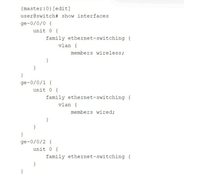
Which statement is correct about the configuration shown in the exhibit?

A. The configuration will not complete the commit check process and will error out.

B. The ge-0/0/0 and ge-0/0/1 interfaces are operating in trunk mode.

C. All three interfaces are operating in access mode.

D. The ge-0/0/2 interface is operating as a Layer 3 interface.

B.   The ge-0/0/0 and ge-0/0/1 interfaces are operating in trunk mode.

Explanation:

On Juniper EX Series switches, when you configure a family ethernet-switching interface with a specific VLAN membership using the vlan statement and the members keyword, the interface defaults to trunk mode if a VLAN name is explicitly listed. The configuration shown for ge-0/0/0 and ge-0/0/1 specifies members wireless and members wired, respectively, without specifying access or trunk explicitly. In Junos, this implicit syntax creates a trunk port that carries only the specified VLAN (as a tagged member unless native-vlan-id is also set). Both interfaces are therefore operating in trunk mode, carrying their respective VLANs.

Why other options are wrong:

A. The configuration will not complete the commit check process and will error out.
Incorrect. The configuration is perfectly valid and will commit successfully. Juniper switches allow trunk ports with a single VLAN member; this is a common way to limit a trunk to only one VLAN. No commit error occurs.


C. All three interfaces are operating in access mode.
Incorrect. Access mode is configured using the interface-mode access statement under ethernet-switching-options or explicitly on the interface. Here, ge-0/0/0 and ge-0/0/1 use the vlan { members ; } syntax without interface-mode access, so they are trunk ports. Only ge-0/0/2 has no VLAN membership configured, so it is not an access port either — it is in its default state (which may be access to VLAN 1 only after other defaults, but that is not explicitly configured). The statement says "all three are access mode" — false because ge-0/0/0 and ge-0/0/1 are trunks.

D. The ge-0/0/2 interface is operating as a Layer 3 interface.
Incorrect. ge-0/0/2 has family ethernet-switching {} with no further configuration. This enables it as a Layer 2 switch port, not a Layer 3 interface. A Layer 3 interface would require family inet with an IP address. The empty ethernet-switching family means the port is a basic Layer 2 port, inheriting default VLAN behavior (typically access VLAN 1 after configuration).

Reference:

Juniper TechLibrary: “Configuring Trunk Ports” – “When you configure vlan members under family ethernet-switching without specifying interface-mode access, the port operates as a trunk port. The specified VLAN is allowed on that trunk.”

JNCIS‑ENT Study Guide (Layer 2 Switching) – “Trunk mode on Juniper is implied when vlan members is used; access mode requires explicit interface-mode access.”

What are two reasons for creating multiple areas in OSPF? (Choose two.)

A. to reduce the convergence time

B. to increase the number of adjacencies in the backbone

C. to increase the size of the LSDB

D. to reduce LSA flooding across the network

A.   to reduce the convergence time
D.   to reduce LSA flooding across the network

Explanation:

A. To reduce the convergence time.
Creating multiple OSPF areas limits the scope of route changes. When a link flaps inside a non‑backbone area, only routers within that area see the Link State Advertisements (LSAs) for that change. Routers in other areas do not receive these Type 1 or Type 2 LSAs — they only see summarized information via Type 3 LSAs from Area Border Routers (ABRs). This containment reduces the number of routers that must recompute their Shortest Path First (SPF) tree, thereby speeding up overall network convergence.

D. To reduce LSA flooding across the network.
Without multiple areas, a single OSPF area floods every LSA to every router in the domain. As the network grows, the volume of LSA flooding increases significantly, consuming bandwidth and CPU cycles on all routers. By dividing the OSPF domain into multiple areas, LSAs are flooded only within their originating area. ABRs filter and summarize routes into other areas, dramatically reducing the total flooding scope.

Why other options are wrong:

B. To increase the number of adjacencies in the backbone.
Incorrect. Multiple areas do not increase adjacencies in the backbone (Area 0). The backbone must remain fully meshed or partially meshed depending on design, but adding areas does not inherently increase backbone adjacencies. In fact, areas can reduce adjacencies by limiting which routers need to become neighbors.

C. To increase the size of the LSDB.
Incorrect. This is the opposite of the goal. A primary benefit of multiple areas is to reduce the size of the Link State Database (LSDB) on individual routers because each router only maintains detailed topology information for its own area plus summarized routes from other areas. A single‑area design results in a large LSDB across all routers; multiple areas shrink LSDB size on most routers.

References:

Juniper TechLibrary: “OSPF Areas and Benefits” – “Multi‑area OSPF reduces LSA flooding, limits route changes to within an area, and improves convergence time.”

JNCIS‑ENT Study Guide (OSPF chapter) – “Creating multiple areas reduces the impact of topology changes, localizes SPF calculations, and reduces LSDB size.”

Exhibit

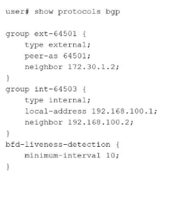
Your BGP neighbors, one in the USA and one in France, are not establishing a connection with each other. Referring to the exhibit, which statement is correct?

A. The BFD liveness is set too low.

B. The BFD liveness must be configured on the BGP neighbor.

C. The BFD liveness must be configured on the BGP group.

D. The BFD liveness is set too high.

A.   The BFD liveness is set too low.

Explanation:

The exhibit shows BFD liveness detection configured globally under edit protocols bgp with minimum-interval 10 milliseconds . However, this aggressive 10ms BFD timer is the direct cause of the BGP session failure between France and the United States.

Why Option A is Correct:

The BFD minimum-interval is clearly set to 10 milliseconds. For intercontinental links (USA to France), the BFD interval must be adjusted significantly upward (e.g., 300ms, 500ms, or 1000ms) to accommodate physical latency . Setting it too low causes rapid timeouts, BFD flapping, and prevents BGP from establishing a stable connection .

Why Other Options Are Incorrect:

B. The BFD liveness must be configured on the BGP neighbor.
— Incorrect. While BFD can be configured at the neighbor level, the exhibit's global configuration under protocols bgp is syntactically correct and applies to all BGP peers unless overridden . The hierarchical structure allows BFD configuration at multiple levels (protocol, group, neighbor) . The issue is the configured value, not the configuration location.

C. The BFD liveness must be configured on the BGP group.
— Incorrect. Similar to option B, BFD configuration at the protocol level (as shown) is perfectly valid and applies to the defined groups (ext-64501 and int-64503) . The bfd-liveness-detection configuration is correctly placed; relocating the same "10" value to the group level would not resolve the session establishment failure.

D. The BFD liveness is set too high.
— Incorrect. This is the opposite of the actual issue. A higher BFD interval (e.g., 1000ms) would be more tolerant of transatlantic latency. The current setting (10ms) is at the lower extreme of the configurable range (1–255,000 milliseconds) and is unsuitable for long-distance links.

Reference:

Juniper CLI Explorer: BFD parameters range 1–255,000 milliseconds
Exam Discussions: JN0-351 question analysis identifies 10ms as too low for USA-France distance
Juniper Documentation: BFD strict mode for BGP peer sessions

Page 2 out of 14 Pages