• 4.9/5.0
  • 72 Questions
  • Updated on: 25-May-2026
  • Enterprise Routing and Switching - Professional (JNCIP-ENT)
  • 172+ Prepared
  • Valid Worldwide

Free JN0-650 Practice Test Questions | Know You're Ready for Enterprise Routing and Switching - Professional (JNCIP-ENT)


Your OSPF network consists of a mix of 1GbE and 10GbE interfaces. By default, all interfaces have the same cost in your OSPF network. You are asked to ensure that the 10GbE interfaces are more preferred when available In this scenario, which two statements would accomplish this behavior? (Choose two.)

A. You should define the reference bandwidth as 10G. which will assign the 1GbE interfaces a higher cost

B. You should manually assign the interface metric for each 10GbE interface to be higher than the 1GbE interfaces in your OSPF network.

C. You should define the reference bandwidth as 1G. which will assign the 1GbE interfaces a higher cost.

D. You should manually assign the interface metric for each 1GbE interface to be higher than the 10GbE interfaces in your OSPF network.

A.   You should define the reference bandwidth as 10G. which will assign the 1GbE interfaces a higher cost
D.   You should manually assign the interface metric for each 1GbE interface to be higher than the 10GbE interfaces in your OSPF network.

Explanation:

To make 10GbE interfaces preferred over 1GbE in OSPF, you need lower OSPF cost on the faster links because OSPF always prefers the path with lowest cost.

A. Define the reference bandwidth as 10G, which will assign the 1GbE interfaces a higher cost. – Correct.
OSPF cost = reference‑bandwidth / interface speed. Default reference (100M) gives both 1G and 10G a cost of 1 (no preference). Changing reference to 10G makes 1GbE cost = 10,000/1,000 = 10 and 10GbE cost = 10,000/10,000 = 1, so 10GbE is preferred.

D. Manually assign the interface metric for each 1GbE interface to be higher than the 10GbE interfaces. – Correct.
Manual metric overrides automatic calculation. Setting a higher cost (e.g., 10) on 1GbE and a lower cost (e.g., 1) on 10GbE directly ensures faster links are preferred.

Why B and C are incorrect

B. Manually assign higher metric to 10GbE interfaces
– Incorrect. This gives faster links a higher cost than slower links, causing OSPF to prefer the slower 1GbE paths—the opposite of what is required.

C. Define reference bandwidth as 1G
– Incorrect. Formula: 1G reference gives 1GbE cost = 1,000/1,000 = 1 and 10GbE cost = 1,000/10,000 = 0.1 (rounded up to 1). Both become 1, so no preference is achieved. Reference must be higher than the fastest link to create differentiation.

References

Juniper TechLibrary – OSPF cost calculation: reference-bandwidth adjusts per‑interface cost based on link speed

RFC 2328 (OSPFv2) – Section 12.3: Cost is inversely proportional to link speed; lower cost is more preferred

Exhibit

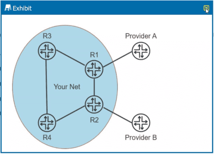
Your network receives the full Internet BGP routing table from two different ISPs. You want your local routers to use Provider A to forward all Internet traffic as long as Provider A is available. Referring to the exhibit, which two actions would satisfy this requirement? (Choose two.)

A. Use a routing policy to set the local preference attribute value higher for the routes that are learned by R1

B. Use a routing policy to set the local preference attribute value higher for the routes that are learned by R2.

C. Use a routing policy to set the local preference attribute value lower for the routes that are learned by R2.

D. Use a routing policy to set the local preference attribute value lower for the routes that are learned by R1.

A.   Use a routing policy to set the local preference attribute value higher for the routes that are learned by R1
C.   Use a routing policy to set the local preference attribute value lower for the routes that are learned by R2.

Explanation:

Local Preference (LocalPref) is a BGP attribute used to influence outbound traffic path selection within an autonomous system. A higher LocalPref value is more preferred. To make Provider A (R1) the preferred path for all Internet traffic when available, you must ensure routes from R1 have a higher LocalPref than routes from R2.

A. Use a routing policy to set the local preference attribute value higher for the routes that are learned by R1.
– Correct. Increasing LocalPref on routes from R1 makes them more preferred than routes with default or lower LocalPref from R2.

C. Use a routing policy to set the local preference attribute value lower for the routes that are learned by R2.
– Correct. Decreasing LocalPref on routes from R2 makes them less preferred, so R1 routes (with default or higher LocalPref) win.

Both actions achieve the same goal: routes from R1 have higher relative LocalPref than routes from R2. You can do one or the other, or both.

Why B and D are incorrect

B. Set LocalPref higher for routes learned by R2
– Incorrect. This would make R2 more preferred, directing traffic toward Provider B instead of Provider A.

D. Set LocalPref lower for routes learned by R1 – Incorrect. This would make R1 less preferred, again steering traffic away from Provider A.

References

Juniper TechLibrary – BGP Local Preference: Higher value is more preferred for outbound route selection

RFC 4271 (BGP-4) – Section 5.1.1: Local Preference attribute

JNCIP-ENT study guide – BGP path selection: LocalPref is the first tie-breaker after highest weight (Cisco) or after next-hop reachability (Juniper)

You must implement EVPN signaling on an EX Series device that is configured with both underlay and overlay networks. Which network protocol accomplishes this task?

A. OSPF underlay network

B. IS-IS underlay network

C. MPLS overlay network

D. EBGP overlay network

D.   EBGP overlay network

Explanation:

EVPN (Ethernet VPN) signaling requires a control plane protocol to exchange MAC, IP, and Ethernet segment reachability information between VTEPs. On EX Series switches in a VXLAN EVPN deployment, this signaling is performed exclusively by MP‑BGP (Multiprotocol BGP) using the evpn address family (AFI 25, SAFI 70). This BGP session is typically established as an EBGP overlay network between loopback interfaces of VTEPs, independent of the underlay routing protocol.

The underlay (OSPF, IS‑IS, or static) provides only IP reachability between VTEP loopbacks. It does not and cannot carry EVPN routes. The overlay BGP EVPN control plane is mandatory for EVPN to function.

Why A, B, and C are incorrect

A. OSPF underlay network
– Incorrect. OSPF can provide underlay IP connectivity (VTEP loopback routes), but it has no mechanism to carry EVPN NLRI. OSPF is completely unaware of EVPN route types.

B. IS‑IS underlay network
– Incorrect. Same limitation as OSPF: IS‑IS handles only underlay routing. EVPN signaling requires BGP, not IS‑IS.

C. MPLS overlay network
– Incorrect. MPLS is a data plane encapsulation method, not a control plane signaling protocol. While EVPN can run over MPLS instead of VXLAN, BGP is still the signaling protocol. Additionally, EX Series switches typically use VXLAN for EVPN overlays, not MPLS.

References

Juniper TechLibrary – EVPN/VXLAN: "EVPN uses MP‑BGP with address family evpn for control plane signaling"

RFC 7432 (EVPN) – Section 7: BGP EVPN NLRI definition

RFC 8365 (NVO3) – Overlay control plane requirements

You have several switches in your network that use Cisco's PVST+ protocol. You want your Juniper switches to interoperate with those devices. In this scenario, which protocol would you use?

A. RPVST+

B. MSTP

C. VSTP

D. RSTP

C.   VSTP

Explanation:

To enable Juniper switches to interoperate with Cisco switches running PVST+ (Per-VLAN Spanning Tree Plus), you must configure VSTP (VLAN Spanning Tree Protocol) on the Juniper devices.

Cisco's PVST+ and Rapid-PVST+ are proprietary per-VLAN spanning tree protocols that are not IEEE standards . Juniper developed VSTP specifically to provide compatibility with Cisco's PVST+ implementation, allowing both vendors' switches to coexist in the same Layer 2 network . Juniper's official documentation explicitly states: "If your EX Series or QFX Series switch interoperates with a Cisco device running Rapid per VLAN Spanning Tree (Rapid PVST+), we recommend that you enable both VSTP and RSTP on the EX Series or QFX Series interface" .

Why other options are incorrect

A. RPVST+
– Incorrect. RPVST+ (Rapid Per-VLAN Spanning Tree Plus) is Cisco's proprietary protocol. Juniper switches do not run RPVST+ natively; they use VSTP to interoperate with it .

B. MSTP
– Incorrect, though it can work. MSTP (Multiple Spanning Tree Protocol) is an IEEE standard (802.1s) that interoperates with Cisco's MST implementation. However, when Cisco switches run PVST+ (not MST), MSTP and PVST+ have well-documented interoperability issues. The PVST Simulation feature can cause ports to block when receiving differing PVST+ BPDUs because Cisco uses Extended System ID (VLAN ID embedded in Bridge ID), making BPDUs for different VLANs non-identical . While technically possible with careful root bridge configuration, VSTP is the Juniper-recommended and more straightforward solution for PVST+ environments .

D. RSTP
– Incorrect. RSTP (Rapid Spanning Tree Protocol) is VLAN-unaware—it runs a single spanning tree instance for all VLANs. Cisco's PVST+ runs a separate instance per VLAN. These two models are fundamentally incompatible and cannot interoperate directly .

References:

Juniper Networks Documentation – VSTP: Designed for Cisco PVST+ interoperability
Cisco Community – MSTP recommended for mixed environments, VSTP also possible
Network Engineering Stack Exchange – PVST+ vs MSTP compatibility issues

Exhibit

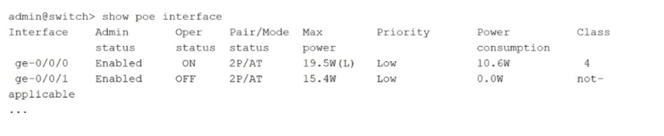
You are deploying a new campus switching environment using various EX Series switch models. The devices attached to one of the new EX Senes switches include IP phones, loT devices, and wireless access points (APs) requiring power over Ethernet (PoE) with varying power requirements. A sample output from one of these switches is shown in the exhibit. In this scenario, which two statements are correct? (Choose two.)

A. The switch is capable of supplying up to 60 W of power to attached PoE devices.

B. Port ge-0/0/0 is enabled and has its maximum power and device class designations statically configured.

C. Port ge-0/0/0 is enabled and has dynamically learned maximum power and device class designations.

D. The switch is capable of supplying up to 30 W of power to attached PoE devices.

B.   Port ge-0/0/0 is enabled and has its maximum power and device class designations statically configured.
D.   The switch is capable of supplying up to 30 W of power to attached PoE devices.

Explanation:

B. Port ge-0/0/0 is enabled and has its maximum power and device class designations statically configured.
– Correct. The show poe interface output shows Max power = 19.5W (L), where (L) indicates a statically configured limit. Class 4 is also manually assigned, overriding dynamic detection. This static mode is used to preserve total power budget.

D. The switch is capable of supplying up to 30 W of power to attached PoE devices.
– Correct. The attached device on ge-0/0/0 is Class 4, which requires PoE+ (802.3at) capability. PoE+ ports can deliver up to 30 W per port, even if a specific port has been administratively limited to 19.5 W.

Why other options are incorrect

A. 60 W capability
– Incorrect. No evidence supports 60 W (PoE‑bt). Class 4 indicates only PoE+ (30 W max per port).

C. Dynamically learned class/power
– Incorrect. Dynamic learning would show default max power (e.g., 30 W for Class 4) without the (L) flag. The (L) and non‑standard 19.5 W value prove static configuration.

References
Juniper TechLibrary – show poe interface: (L) indicates statically configured maximum power
Juniper CLI Reference – Static PoE management mode overrides dynamic class defaults
IEEE 802.3at – PoE+ Class 4 requires 30 W PSE capability per port

You run a multivendor switching environment where you have configured VSTP. You have 450 VLANs and notice that some of your VLANs do not function properly. How should you change the configuration to get all 450 VLANs working?

A. Include the force-version stp; statement in your configuration

B. Enable RSTP to handle additional VLANs.

C. Set the VLAN max-age to 3600 or more.

D. Increase the bridge priority on all VLANs to at least 16k.

B.   Enable RSTP to handle additional VLANs.

Explanation:

VSTP (VLAN Spanning Tree Protocol) has a hard limit on the number of VLANs it can support. On EX Series switches running Junos OS that does not support Enhanced Layer 2 Software (ELS), the maximum is 253 VLANs . When you exceed this limit—as you are with 450 VLANs—some VLANs will not function properly because they are not covered by any spanning-tree protocol.

The solution is to enable RSTP alongside VSTP. RSTP is already enabled by default on EX Series switches . When both protocols are configured concurrently, VSTP handles up to its maximum supported VLANs, while RSTP automatically provides spanning-tree coverage for the remaining VLANs. This is the Juniper-recommended best practice .

Enabling RSTP adds minimal overhead and ensures that all VLANs have a loop-prevention mechanism, resolving the issue.

Why other options are incorrect

A. force-version stp – Incorrect. This forces the spanning-tree version to original IEEE 802.1D STP . It does not increase the VLAN limit or fix the problem.

C. Set max-age to 3600 – Incorrect. Max-age controls how long BPDUs are retained and influences convergence timing . It does not affect how many VLANs VSTP can support.

D. Increase bridge priority to 16k – Incorrect. Bridge priority influences root bridge election , not the number of VLANs that can run VSTP.

References
Juniper Manuals – VSTP limit: 253 VLANs on non-ELS EX Series
Juniper Pathfinder – RSTP and VSTP concurrent configuration support
Juniper Best Practice – "Configure RSTP when you configure VSTP" to cover all VLANs

Exhibit.

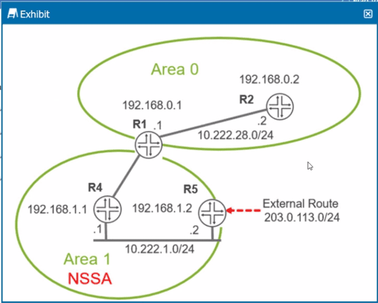
Referring to the exhibit, which two statements are correct? (Choose two.)

A. R1 will advertise the 203 0.113.0724 route as an OSPF Type 7 LSA into Area 0.

B. R5 will advertise the 203 0.113 0/24 route as an OSPF Type 5 LSA into Area 1.

C. R1 will advertise the 203 0.113.0/24 route as an OSPF Type 5 LSA into Area 0

D. R5 will advertise the 203 0.113.0/24 route as an OSPF Type 7 LSA into Area 1.

C.   R1 will advertise the 203 0.113.0/24 route as an OSPF Type 5 LSA into Area 0
D.   R5 will advertise the 203 0.113.0/24 route as an OSPF Type 7 LSA into Area 1.

Explanation:

The question involves the route 203.0.113.0/24 and OSPF LSA types Type 5 (AS External) and Type 7 (NSSA External). Type 7 LSAs are used only in Not-So-Stubby Areas (NSSA) and are translated by the ABR into Type 5 LSAs when they leave the NSSA.

C. R1 will advertise the 203.0.113.0/24 route as an OSPF Type 5 LSA into Area 0 – Correct if:
R1 is an ABR between an NSSA (Area 1) and Area 0.
The route originates as a Type 7 LSA in Area 1 (from R5).
R1, as the ABR, translates Type 7 into Type 5 and floods into Area 0.


D. R5 will advertise the 203.0.113.0/24 route as an OSPF Type 7 LSA into Area 1 – Correct if:
R5 is an ASBR inside an NSSA (Area 1).
By definition, an ASBR in an NSSA injects external routes as Type 7 LSAs, not Type 5.

Why A and B are incorrect

A. R1 advertises Type 7 into Area 0
– Incorrect. Type 7 LSAs never leave an NSSA. They are blocked by ABRs and optionally translated to Type 5.

B. R5 advertises Type 5 into Area 1
– Incorrect. If Area 1 is an NSSA, an ASBR inside it must generate Type 7, not Type 5.

References
RFC 2328 (OSPFv2): Type 5 vs Type 7 behavior
RFC 3101 (NSSA): Type 7 LSAs originate in NSSA; ABR translates Type 7 → Type 5
Juniper TechLibrary: NSSA configuration and LSA types

An incorrectly configured routing policy at your service provider led to several hundred thousand routes being placed in your edge router's routing table In this scenario, how would you limit the number of prefixes received on a BGP peer session?

A. Enable the damping BGP parameter in the edge router configuration

B. Enable the prefix-limit BGP parameter in the edge router configuration.

C. Enable the graceful-restart BGP parameter in the edge router configuration.

D. Enable the advertise-inactive BGP parameter in the edge router configuration.

B.   Enable the prefix-limit BGP parameter in the edge router configuration.

Explanation:

The prefix-limit BGP parameter allows you to set a maximum number of prefixes that can be accepted from a BGP peer. When the limit is exceeded, the router can take actions such as:

Log a warning (default)
Shut down the BGP session to protect the router from memory exhaustion

This directly addresses the scenario of an incorrectly configured routing policy injecting hundreds of thousands of unwanted routes into the routing table.

Why other options are incorrect

A. damping
– Incorrect. BGP route damping is used to suppress unstable routes that flap (frequently appear and disappear). It reduces churn but does not limit the number of prefixes received.

C. graceful-restart
– Incorrect. Graceful restart allows a BGP session to recover without disrupting forwarding during a control plane restart. It has no effect on the number of prefixes received.

D. advertise-inactive
– Incorrect. This parameter controls whether inactive routes (non-best paths) are advertised to peers. It does not limit prefix count.

References

Juniper TechLibrary – prefix-limit BGP configuration
JNCIP-ENT Study Guide – BGP prefix limiting for route flood protection
RFC 4271 – BGP-4; prefix limits are an implementation-specific feature

Page 3 out of 9 Pages