• 4.9/5.0
  • 72 Questions
  • Updated on: 25-May-2026
  • Enterprise Routing and Switching - Professional (JNCIP-ENT)
  • 172+ Prepared
  • Valid Worldwide

Free JN0-650 Practice Test Questions | Know You're Ready for Enterprise Routing and Switching - Professional (JNCIP-ENT)


Your Layer 2 network uses 802.1X to authenticate user devices connecting to the network. You are asked to include a new Layer 2 interface connection from the conference room in your network. You must ensure that only a single device is allowed to authenticate on this port at one time to avoid users from being able to plug in a rogue switch to this port. In this scenario, which 802.1X method would you use for the new interface?

A. single-secure supplicant mode

B. multiple supplicant mode

C. single supplicant mode

D. MAC-RADIUS

A.   single-secure supplicant mode

Explanation:

To restrict a port so that only one device is allowed to authenticate at a time, you must use the single-secure supplicant mode. This mode authenticates the first end device that attempts to connect and then prevents any additional devices from authenticating on that port—even if they provide valid credentials—unless the first device logs out.

This directly addresses the requirement to prevent users from plugging in a rogue switch (which would appear as multiple devices behind a single port).

Why other options are incorrect

B. multiple supplicant mode
– Incorrect. This mode allows multiple devices to authenticate simultaneously on the same port. Each device is individually authenticated, but this would defeat the security requirement because a rogue switch could be connected and multiple devices behind it would all be authenticated.

C. single supplicant mode
– Incorrect. This mode authenticates only one device as well, but unlike single-secure, it does not block additional devices. Instead, if a second device is detected, the switch shuts down the port or forces re-authentication of the first device—depending on configuration. More importantly, single-secure is the Juniper-recommended method for explicitly limiting to exactly one authenticated client at a time.

D. MAC-RADIUS
– Incorrect. MAC-RADIUS bypasses 802.1X and uses only the device's MAC address for authentication. While you can still limit the number of MAC-authenticated devices, the standard method for preventing multiple devices on a single port with 802.1X is the single-secure supplicant mode, not MAC-RADIUS alone.

References:

Juniper TechLibrary – "802.1X Authentication – Single-Secure Supplicant Mode"
JNCIP-ENT Study Guide – Port Authentication (802.1X) Policies
Juniper EX Series Configuration Guide – Access Control and Authentication

Which two statements are correct about EVPN/VXLAN deployments? (Choose two.)

A. VNIs are used for encapsulating and de-encapsulating traffic entering and leaving the tunnels

B. VTEPs are used for encapsulating and de-encapsulating traffic entering and leaving the tunnels.

C. VTEPs are used to identify broadcast domains within an EVPN/VXLAN environment.

D. VNIs are used to identify broadcast domains within an EVPN/VXLAN environment.

B.   VTEPs are used for encapsulating and de-encapsulating traffic entering and leaving the tunnels.
D.   VNIs are used to identify broadcast domains within an EVPN/VXLAN environment.

Explanation:

B. VTEPs are used for encapsulating and de-encapsulating traffic entering and leaving the tunnels.
– Correct. A VTEP (VXLAN Tunnel Endpoint) is the device that performs the encapsulation and decapsulation of VXLAN frames. When a frame enters a VXLAN tunnel, the source VTEP wraps the original Ethernet frame with a VXLAN header, UDP header, and outer IP header. When the frame exits the tunnel, the destination VTEP removes these headers and forwards the original Ethernet frame to the destination host.

D. VNIs are used to identify broadcast domains within an EVPN/VXLAN environment.
– Correct. A VNI (VXLAN Network Identifier) is a 24-bit identifier included in the VXLAN header that uniquely identifies a Layer 2 broadcast domain or segment. Each VNI corresponds to a virtual network, allowing up to 16 million unique segments. This enables the separation of traffic from different tenants or different VLANs within the same physical infrastructure.

Why A and C are incorrect

A. VNIs are used for encapsulating and de-encapsulating traffic entering and leaving the tunnels.
– Incorrect. VNIs are identifiers carried inside the VXLAN header, but they do not perform the encapsulation/de-encapsulation action. That action is performed by VTEPs. Think of the VNI as a tag, while the VTEP is the device that reads and writes that tag.

C. VTEPs are used to identify broadcast domains within an EVPN/VXLAN environment.
– Incorrect. VTEPs are the tunnel endpoints; they do not serve as identifiers for broadcast domains. Broadcast domains are identified by VNIs. While a VTEP may be configured with multiple VNIs, the VTEP itself is not an identifier.

References:

RFC 7348 – VXLAN architecture (VTEP and VNI definitions)
Juniper TechLibrary – EVPN/VXLAN overview
JNCIP-ENT Study Guide – VXLAN component role

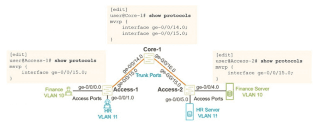
Exhibit

You configured MVRP in your Layer 2 network using the configuration shown in the exhibit. You verified that the appropnate VLANs are configured and applied on the two access switches. You are using RSTP as your loop prevention mechanism. Unfortunately, the users are not able to communicate with their corresponding server attached to the Access- 2 switch. In this scenario, what should you do to solve this problem?

A. Configure VSTP instead of RSTP as your loop-prevention mechanism.

B. Configure the access interfaces on the Access-2 switch under MVRP.

C. Configure the ge-070716.0 interface on the Core-1 switch under MVRP.

D. Configure the access interfaces on the Access-1 switch under MVRP.

C.   Configure the ge-070716.0 interface on the Core-1 switch under MVRP.

Explanation:

MVRP (Multiple VLAN Registration Protocol) dynamically propagates VLAN registration information across trunk ports. In the exhibit:

Access‑1 has VLAN 10 (Finance) and VLAN 11 (HR) configured on its access ports, and MVRP enabled on trunk interface ge-0/0/15.0 (toward Core‑1).

Access‑2 has VLAN 10 (Finance Server) and VLAN 11 (HR Server) configured, and MVRP enabled on trunk interface ge-0/0/15.0 (toward Core‑1).

Core‑1 has MVRP enabled on ge-0/0/15.0 (toward Access‑1) and also needs MVRP enabled on ge-0/0/14.0 to allow the VLAN declarations from Access‑1 to propagate to Access‑2.

Without MVRP on ge-0/0/14.0 on Core‑1, the VLAN registration information from Access‑1 does not reach Access‑2. The users on Access‑1 cannot communicate with their servers on Access‑2 because the trunk segments are not dynamically propagating the VLAN membership across the entire path.

Why other options are incorrect

A. Configure VSTP instead of RSTP
– Incorrect. The problem is not related to STP type. VSTP (VLAN Spanning Tree Protocol) is used for per‑VLAN STP in mixed‑vendor environments, but RSTP works fine here. The issue is MVRP propagation, not loop prevention.

B. Configure the access interfaces on Access‑2 under MVRP
– Incorrect. MVRP is only needed on trunk ports to propagate VLAN registrations. Access ports (where end hosts connect) do not need MVRP because they are statically assigned to VLANs.

D. Configure the access interfaces on Access‑1 under MVRP
– Incorrect. Access ports on Access‑1 (e.g., ge-0/0/0.0 for Finance, ge-0/0/1.0 for HR) do not need MVRP. Their VLAN membership is statically configured, and they do not propagate VLAN registrations further.

References:

Juniper TechLibrary – MVRP configuration: MVRP must be enabled on all trunk interfaces in the propagation path

JNCIP‑ENT study guide – VLAN registration protocols (MVRP)

You are troubleshooting a multicast deployment in a network. Some multicast groups operate in PIM-ASM mode and others operate in PIM-SSM mode. While troubleshooting, you note the following:
- The network uses IGMPv2 for some segments and IGMPv3 for others.
- For group 232.1.1.1, receivers know the exact source IP of the multicast sender
- For group 239.10.10.10. receivers do not know the source address in advance.
Which two statements correctly describe the operational differences between these two modes in Junos OS? (Choose two.)

A. PIM-ASM supports multiple active sources for a group without requiring receivers to know them in advance, whereas PIM-SSM requires explicit source knowledge

B. In PIM-ASM. the DR first sends a PIM register message to the RP before switching to the shortest-path tree.

C. PIM-SSM requires an RP for initial joins, whereas PIM-ASM can operate without one.

D. PIM-SSM relies on IGMPv3 to signal both the source and the group in the join message, bypassing the RP entirely.

A.   PIM-ASM supports multiple active sources for a group without requiring receivers to know them in advance, whereas PIM-SSM requires explicit source knowledge
D.   PIM-SSM relies on IGMPv3 to signal both the source and the group in the join message, bypassing the RP entirely.

Explanation:

A. PIM-ASM supports multiple active sources for a group without requiring receivers to know them in advance, whereas PIM-SSM requires explicit source knowledge.
– Correct. Any-Source Multicast (ASM) allows any source to send to a multicast group, and receivers join the group without knowing the source IP in advance. Source-Specific Multicast (SSM) requires receivers to know both the source IP and the group IP at join time, typically signaled via IGMPv3's INCLUDE mode, which specifies (S,G) instead of just (*,G).

D. PIM-SSM relies on IGMPv3 to signal both the source and the group in the join message, bypassing the RP entirely.
– Correct. SSM uses IGMPv3's capability to report (S,G) membership. When the receiver's DR receives this, it sends a PIM (S,G) join directly toward the source (without ever involving an RP). This eliminates the need for an RP, shared tree, or register process. In contrast, ASM typically uses IGMPv1/v2 (or IGMPv3 in EXCLUDE mode), which only signals (*,G), requiring RP-based shared trees initially.

Why B and C are incorrect

B. In PIM-ASM, the DR first sends a PIM register message to the RP before switching to the shortest-path tree.
– Incorrect as a difference between ASM and SSM. This describes PIM-ASM behavior accurately, but the question asks for operational differences between the two modes. This statement is true only for ASM, but SSM never uses an RP or register messages at all. However, the wording of the question expects contrasting statements about both modes. Since SSM has no RP, this does not correctly describe a difference of the same type for both modes — and more importantly, this is a description of ASM only, not a valid paired difference.

C. PIM-SSM requires an RP for initial joins, whereas PIM-ASM can operate without one.
– Incorrect. This is backwards. PIM-ASM requires an RP for initial joins (via shared tree), while PIM-SSM does not require an RP at all because joins are sent directly toward the source using (S,G) state.

References

Juniper TechLibrary – PIM-SSM overview: "SSM uses IGMPv3 to join (S,G) directly without an RP"

Juniper TechLibrary – PIM-ASM overview: "ASM uses an RP for shared tree and register process"

Which statement about LLDP and LLDP-MED operations on EX Series devices is correct?

A. LLDP only operates on interfaces configured for Layer 2

B. EX Series devices flood LLDP frames across a Layer 2 domain to calculate a network topology

C. EX Series devices support LLDP-MED power negotiation, enabling dynamic allocation of PoE power based on endpoint device needs.

D. LLDP-MED focuses on discovering network connectivity devices like routers and switches.

C.   EX Series devices support LLDP-MED power negotiation, enabling dynamic allocation of PoE power based on endpoint device needs.

Explanation:

C is correct because LLDP-MED (Link Layer Discovery Protocol
- Media Endpoint Discovery) is an extension to standard LLDP specifically designed for communication between network switches and endpoint devices such as IP phones, cameras, and wireless access points . One of its key features is the Power Management TLV (Type-Length-Value), which enables advanced Power over Ethernet negotiation. When an LLDP-MED capable device connects to an EX Series switch, it can communicate its exact power requirements to the switch, allowing dynamic allocation of PoE power based on the device's needs rather than relying on static power classes . This optimizes the switch's power budget and ensures devices receive only the power they actually require.

Why A is incorrect: The statement "LLDP only operates on interfaces configured for Layer 2" is false. LLDP is a Layer 2 protocol that runs over the data-link layer, but it is not restricted to interfaces configured exclusively for Layer 2 switching. LLDP operates on physical interfaces regardless of whether they are configured for Layer 2 or Layer 3 operations . It discovers neighbors and advertises information about the device itself, not about the Layer 2/Layer 3 configuration of the interface.

Why B is incorrect: EX Series devices do not flood LLDP frames across a Layer 2 domain to calculate network topology. LLDP is a neighbor discovery protocol that operates on a point-to-point basis—each device communicates directly with its immediate neighbors only. LLDP frames are not flooded; they are transmitted to a specific multicast MAC address (01:80:C2:00:00:0E) and are not forwarded by switches beyond the directly connected link . Topology calculation using LLDP would require central collection of neighbor information (e.g., via a network management system), not flooding.

Why D is incorrect: LLDP-MED does not focus on discovering network connectivity devices like routers and switches. That is the function of standard LLDP. LLDP-MED is specifically designed for media endpoint devices such as IP phones, video conferencing systems, and other voice/video endpoints . LLDP-MED extends LLDP with additional TLVs for VoIP applications, including network policy discovery (VLAN, CoS, DSCP), power management, inventory management, and location information for emergency services (e.g., E911) .

References:

Juniper Networks Documentation: LLDP-MED power negotiation capabilities on EX Series switches

Cisco Configuration Guide: LLDP-MED Power Management TLV for dynamic power allocation

You want to implement a system in your network to simplify VLAN management that can also dynamically create and prune VLANs. How would you accomplish this task?

A. Enable GVRP on access interfaces.

B. Enable MVRP and GVRP on all interfaces.

C. Enable MVRP on trunk interfaces.

D. Enable MVRP on access interfaces.

C.   Enable MVRP on trunk interfaces.

Explanation:

MVRP (Multiple VLAN Registration Protocol) is the IEEE 802.1ak standard that dynamically manages VLAN registration information across a Layer 2 network. When enabled on trunk interfaces, MVRP allows switches to automatically:

Dynamically create VLANs based on declarations from neighboring switches
Prune VLANs when they are no longer needed by any switch in the network
Propagate VLAN membership information only across trunk links that require specific VLANs

This simplifies VLAN management by eliminating the need to manually configure the same VLANs on every switch's trunk ports. When a switch declares a VLAN (because it has an access port in that VLAN), MVRP carries that declaration across trunk interfaces, and only trunk interfaces that need that VLAN will dynamically register and carry its traffic.

Why other options are incorrect

A. Enable GVRP on access interfaces – Incorrect. GVRP (GARP VLAN Registration Protocol) is an older, less robust protocol than MVRP. Even if GVRP were used, access interfaces do not need dynamic VLAN registration because they are statically assigned to VLANs. Dynamic registration is designed for trunk links between switches.

B. Enable MVRP and GVRP on all interfaces– Incorrect. Running both protocols concurrently is unnecessary and may cause conflicts. MVRP is the successor to GVRP and is the recommended protocol for Juniper EX Series switches. Additionally, enabling either protocol on access interfaces serves no practical purpose.

D. Enable MVRP on access interfaces – Incorrect. Access interfaces connect to end devices (servers, workstations) that do not participate in VLAN registration protocols. Enabling MVRP on access interfaces provides no benefit and may cause unnecessary processing overhead.

References:
Juniper TechLibrary – MVRP: "MVRP dynamically registers and deregisters VLANs on trunk interfaces"
IEEE 802.1ak – Multiple Registration Protocol (MRP) and MVRP specifications
JNCIP-ENT study guide – Layer 2 protocols: MVRP for dynamic VLAN management and pruning

Which three statements about VSTP are correct? (Choose three.)

A. Separate BPDUs are Hooded for each VSTP enabled VLAN.

B. VSTP is incompatible with RSTR

C. VSTP is enabled by default on EX Series switches.

D. VSTP supports up to 253 unique spanning tree topologies.

E. A separate spanning tree instance is generated for each VLAN.

A.   Separate BPDUs are Hooded for each VSTP enabled VLAN.
D.   VSTP supports up to 253 unique spanning tree topologies.
E.   A separate spanning tree instance is generated for each VLAN.

Explanation:

A. Separate BPDUs are flooded for each VSTP enabled VLAN.
– Correct. VLAN Spanning Tree Protocol (VSTP) operates on a per‑VLAN basis. For each VLAN enabled for VSTP, the switch generates and floods separate BPDUs specific to that VLAN. This allows different VLANs to have different spanning tree topologies, including independent root bridges, port roles, and states.

D. VSTP supports up to 253 unique spanning tree topologies.
– Correct. Juniper EX Series switches support up to 253 VSTP instances (VLANs) simultaneously. This limit accounts for system resource constraints (CPU and memory), as each VSTP instance maintains its own spanning tree state machine, timers, and BPDU processing.

E. A separate spanning tree instance is generated for each VLAN.
– Correct. The core principle of VSTP is to create an independent spanning tree instance per VLAN. Unlike RSTP (which uses a single instance for all VLANs) or MSTP (which maps multiple VLANs to fewer instances), VSTP dedicates one spanning tree topology per VLAN, providing maximum flexibility at the cost of higher resource consumption.

Why B and C are incorrect

B. VSTP is incompatible with RSTP.
– Incorrect. VSTP is actually an extension of RSTP (IEEE 802.1w) and operates on a per‑VLAN basis. VSTP uses the same rapid convergence mechanisms as RSTP, including proposal/agreement handshake and edge port detection. VSTP is fully compatible with RSTP when VLAN consistency is maintained across the Layer 2 domain. The statement confuses "incompatible" with "different scope" (single instance vs. multiple instances).

C. VSTP is enabled by default on EX Series switches.
– Incorrect. By default, Juniper EX Series switches run RSTP (Rapid Spanning Tree Protocol) on all interfaces. VSTP must be explicitly configured under [edit protocols vstp] after disabling RSTP or other spanning tree protocols. VSTP is not the default STP mode.

References:

Juniper TechLibrary – VSTP: "VSTP runs a separate spanning tree instance per VLAN, with up to 253 instances supported"

Juniper EX Series Configuration Guide – Spanning Tree Protocols: RSTP is default, VSTP requires explicit configuration

You need to perform maintenance on one of your OSPF routers. You do not want the other OSPF routers on the network to forward traffic to this router dunng the maintenance window Which OSPF configuration parameter would you implement to accomplish this task?

A. traffic-engineering

B. overload

C. preference

D. spf-options

B.   overload

Explanation:

To prevent other OSPF routers from forwarding transit traffic through a router during maintenance, you need to configure the overload feature (also known as stub router or max-metric). When enabled, the router signals to neighbors that it should not be used for transit traffic, while still allowing traffic destined for its directly connected networks.

Why other options are incorrect

A. traffic-engineering
– Incorrect. MPLS traffic engineering is used to influence path selection based on constraints like bandwidth or administrative groups, not to temporarily prevent a router from carrying transit traffic during maintenance. This is a fundamentally different operational purpose.

C. preference
– Incorrect. The preference parameter adjusts the administrative distance of OSPF routes relative to other routing protocols. It does not signal other OSPF routers to avoid using a router for transit traffic. This controls local route selection only.

D. spf-options
– Incorrect. The spf-options stanza configures SPF calculation parameters such as delay timers or rapid updates. It does not provide the overload/stub router advertisement functionality needed to repel transit traffic during maintenance .

References:
Juniper TechLibrary – overload configuration for repelling transit traffic
RFC 3137 – OSPF Stub Router Advertisement (overload mechanism)
Juniper CLI reference – set protocols ospf overload

Page 2 out of 9 Pages