- 4.9/5.0
- 64 Questions
- Updated on: 12-Oct-2026
- Data Center - Specialist (JNCIS-DC)
- 164+ Prepared
- Valid Worldwide
Free JN0-481 Practice Test Questions | Know You're Ready for Data Center - Specialist (JNCIS-DC)
You are trying to deploy a five-stage template to a blueprint as shown in the exhibit. You
cannot see your template name in the list of available templates.
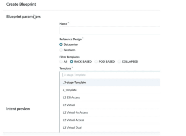
In this scenario, which statement is correct?
A. The Collapsed option should be selected.
B. You must include “five-stage” in the template name for it to appear in the list.
C. The Pod Based option should be selected.
D. Only Freeform-type blueprints support five-stage templates.
Explanation:
In Juniper Apstra, the template type determines the fabric architecture you are building. When creating a blueprint, the available templates are filtered based on the Reference Design and the Filter Templates options selected .
Why other options are incorrect:
A. The Collapsed option should be selected.
— The Collapsed filter is used for collapsed fabric architectures (spineless designs), not for five-stage fabrics . Selecting this would still not display your pod-based five-stage template.
B. You must include "five-stage" in the template name for it to appear in the list.
— Template names in Apstra are user-defined strings . There is no keyword requirement such as "five-stage" for a template to be listed. The filtering mechanism is based on the template type setting (Rack Based, Pod Based, or Collapsed), not on name matching.
D. Only Freeform-type blueprints support five-stage templates.
— This is incorrect. The Datacenter reference design fully supports five-stage fabrics using pod-based templates . Freeform blueprints are used for non-standard designs or heterogeneous environments and are not required for standard five-stage Clos deployments.
Reference:
Juniper Networks Documentation
— *"Pod-based templates are for designing a 5-stage fabric (that is, linking multiple rack-based templates to a superspine)"* ; "From the left navigation menu, navigate to Design > Templates and click Create Template... select POD BASED" ;
You are creating a new security policy using Juniper Apstra.
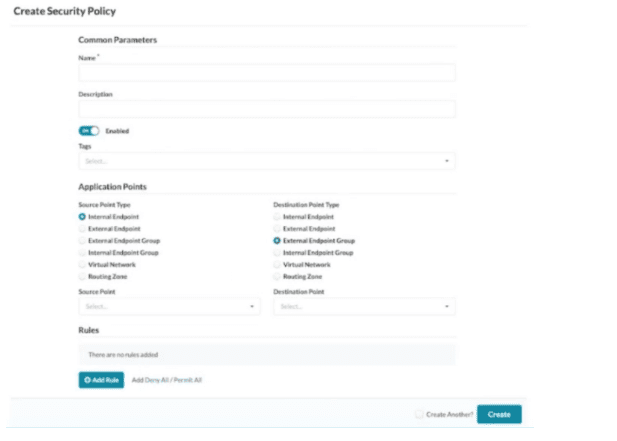
Referring to the exhibit, which application point should you select to allow or deny traffic to
or from a particular VRF?
A. Routing Zone
B. External Endpoint
C. Internal Endpoint
D. Virtual Network
Explanation:
In Juniper Apstra, a Routing Zone (RZ) directly aligns with a Virtual Routing and Forwarding (VRF) instance . VRFs provide isolation at the routing table level, separating tenants so they cannot reach each other at Layer 3. If you want to allow or deny traffic to or from an entire VRF, you must select the Routing Zone as the application point in your security policy.
The Juniper Apstra documentation explicitly states: "Routing Zones (RZ) are the highest-level objects. RZ is directly aligned with a Virtual Routing and Forwarding instance (VRF)" . When creating security policies, the source or destination object can be selected from Routing Zones (all Virtual Networks within an SZ) . This means selecting a Routing Zone applies the policy to all Virtual Networks contained within that VRF, effectively controlling traffic to or from a particular VRF as a whole.
Why other options are incorrect:
B. External Endpoint
— External endpoints represent IP ranges or subnets outside the Apstra blueprint . These are used for traffic flowing between the fabric and external networks (e.g., WAN gateways, firewalls), not for applying policy to an entire VRF.
C. Internal Endpoint
— Internal endpoints are specific IP addresses (typically /32) associated with Virtual Networks inside the blueprint . These are granular objects for host-level policies, not for controlling all traffic within an entire VRF.
D. Virtual Network
— A Virtual Network represents a single L2/L3 segment (VXLAN or VLAN). Selecting a Virtual Network applies policy only to that specific network, not to all networks within the VRF . To cover an entire VRF (multiple Virtual Networks), you must select the Routing Zone instead.
Reference:
Juniper Networks TechLibrary — "Security Policies: Routing Zones (RZ) are the highest-level objects. RZ is directly aligned with a Virtual Routing and Forwarding instance (VRF)."
Juniper Networks TechLibrary — "Security policies allow or block traffic between endpoints based on their IP addresses, port numbers, and protocols... Routing Zone (RZ) which are rendered as Virtual Routing and Forwarding (VRF) instances on physical devices."
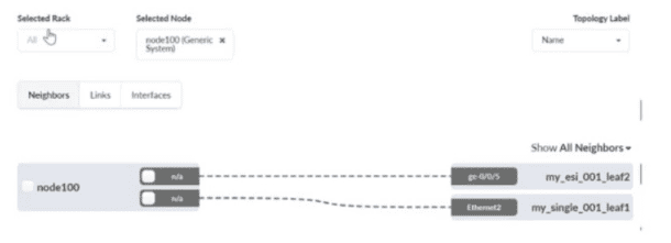
What is correct about the selected device shown in the exhibit?
A. It is a peer switch.
B. It is an external generic system.
C. It is an internal generic system.
D. It is an access switch.
Explanation:
In Juniper Apstra, a Generic System represents a device that is not managed by Apstra but is connected to the managed fabric . The distinction between internal and external generic systems is determined by the device's physical location and connectivity scope .
Why other options are incorrect:
A. It is a peer switch
A peer switch would be a managed network device (leaf or spine). The label "Generic System" indicates it is unmanaged by Apstra .
B. It is an external generic system
External generic systems are used for middleware devices (firewalls, load balancers, external routers) that may connect to multiple racks for redundancy . They appear outside rack structures . The device here is within a selected rack, making it internal.
D. It is an access switch
Access switches are managed network devices, not generic systems. The labeling and UI representation clearly show this as a "Generic System," not a switch .
Reference:
Juniper Networks TechLibrary: "Systems that are not managed by Apstra and that are part of a rack topology are called (internal) generic systems"
Juniper Networks TechLibrary: "Generic System — For attaching compute/storage, Can only be connected to a single rack, Appears in the topology as part of a rack"
You have created a blueprint and are in the process of assigning systems. You require the
leaf3-sonic device in the blueprint but do not want it to actively participate in the routing of
the IP fabric.
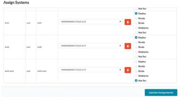
In the Juniper Apstra UI, which two modes satisfy this requirement? (Choose two.)
A. Drain
B. Ready
C. Deploy
D. Undeploy
D. Undeploy
Explanation:
In Juniper Apstra, the requirement is to have the leaf3-sonic device included in the blueprint but prevent it from actively participating in IP fabric routing. Both Drain and Undeploy modes satisfy this requirement, though they achieve it at different stages of the device lifecycle.
A. Drain Mode
gracefully removes a device from service for maintenance while keeping it assigned to the blueprint. When a device is set to Drain mode, Apstra applies changes to BGP policies and disables/shuts down all L2 ports, effectively taking the device out of service without disrupting existing TCP flows. The device remains in the blueprint but does not route traffic or participate in control plane operations. This is explicitly designed for taking a device out of service for maintenance or decommissioning.
D. Undeploy Mode
completely removes Apstra-rendered configuration from the device. Documentation states that if a device is carrying traffic, it is best to first put the device into Drain mode (and commit the change) before proceeding to Undeploy. Like Drain, Undeploy keeps the device assigned to the blueprint but ensures it does not actively participate in IP fabric routing. Undeploy is the appropriate mode for a device you want in the blueprint but fully inactive.
Why other options are incorrect:
B. Ready Mode
— This mode places the device in a Discovery-2 state where it receives complete configuration (hostname, interface descriptions, port speeds) but no BGP configuration. Interfaces are brought up and LLDP is enabled, allowing Apstra to validate cabling and telemetry. However, this does not prevent the device from participating in fabric operations. The device remains ready for service deployment and is not removed from routing participation.
C. Deploy Mode
— This mode adds full service configuration including BGP, puts the device fully in service, and actively participates in IP fabric routing. This is the opposite of what the requirement asks for.
Reference:
Juniper Networks TechLibrary — "Drain — Takes a device out of service for maintenance" and "Undeploy — Removes Apstra-rendered configuration"
Juniper Networks TechLibrary — *"Set deploy mode to Drain ... applies changes to BGP policies and disables/shuts down all L2 ports"*
| Page 2 out of 8 Pages |