- 4.9/5.0
- 65 Questions
- Updated on: 12-Jun-2026
- Data Center Associate (JNCIA-DC)
- 165+ Prepared
- Valid Worldwide
Free JN0-281 Practice Test Questions | Know You're Ready for Data Center Associate (JNCIA-DC)
What is the purpose of implementing a link aggregation group LAG in a network?
A. to provide redundancy and load balancing across multiple links
B. to encrypt traffic between switches
C. to increase the speed of a single physical interface
D. to assign IP addresses automatically to devices on a network
Explanation:
Why A is correct:
LAG provides both redundancy (link‑level fault tolerance) and load balancing (bandwidth aggregation). These are the two core benefits defined in IEEE 802.1AX (formerly 802.3ad).
Why other options are incorrect (briefly):
B. to encrypt traffic between switches
– Encryption is provided by protocols like MACsec, IPsec, or TLS. LAG is purely a link‑aggregation technology and offers no encryption or security features.
C. to increase the speed of a single physical interface
– LAG does not turn four 1 Gbps links into one 4 Gbps logical interface in terms of a single flow. A single flow is pinned to one member link (hash‑dependent), so it does not exceed the speed of one member. The aggregate bandwidth is available for multiple parallel flows, not for accelerating a single stream.
D. to assign IP addresses automatically to devices on a network
– Automatic IP address assignment is performed by DHCP (Dynamic Host Configuration Protocol) , not LAG.
References:
Juniper TechLibrary – Link Aggregation (LAG)
"A LAG increases bandwidth, provides redundancy, and load‑balances traffic across multiple physical links. If one link fails, traffic is redistributed among the remaining links."
g-link-aggregation.html
IEEE 802.1AX-2020 – Link Aggregation Standard
"The purpose of link aggregation is to provide increased bandwidth, graceful degradation as failures occur, and load sharing."
Which statement about the qualified next-hop feature is correct when configuring a static route?
A. Qualified next-hop is used for specifying redundant next-hops.
B. Qualified next-hop is used when the next-hop address is not within the route table of the local device.
C. Qualified next-hop is only required when a link-state protocol is configured.
D. Qualified next-hop uses pings to verify that the next hop is up.
Explanation:
The qualified next-hop feature in Junos OS allows you to configure multiple next-hop addresses for a single static route, each with its own preference (administrative distance) value. This enables redundant paths with deterministic failover behavior.
Why A is correct:
Qualified next-hops are specifically designed to provide redundancy. You define a primary next hop (with default or lower preference) and one or more secondary (backup) next hops with higher preference values (less preferred). If the primary next hop becomes unreachable, the route with the next lowest preference automatically takes over. This creates a floating static route scenario without requiring dynamic routing protocols.
Why other options are incorrect (briefly):
B. Qualified next-hop is used when the next-hop address is not within the route table of the local device.
– Incorrect. If a next-hop address is not in the routing table, the static route will not be installed. The resolve feature (not qualified next-hop) allows indirect resolution through other routes. Qualified next-hop still requires reachable next-hop addresses.
C. Qualified next-hop is only required when a link-state protocol is configured.
– Incorrect. Qualified next-hop is a static route feature and has no requirement or dependency on any dynamic routing protocol (link‑state or otherwise). It works independently.
D. Qualified next-hop uses pings to verify that the next hop is up.
– Incorrect. By default, static routes (including qualified next-hops) rely on route reachability through the routing table, not ICMP pings. Optional passive monitoring or BFD can be used separately, but pings are not part of qualified next-hop functionality.
References:
Juniper TechLibrary – Qualified Next Hops for Static Routes
"Qualified next hops allow you to specify multiple redundant next hops for a static route, each with its own preference. The route with the lowest preference is used."
JNCIA-DC Certification Guide, Domain 3 (Routing)
"Qualified next hops provide redundant path support for static routes without requiring dynamic routing protocols. Each backup path gets its own preference value."
According to Juniper Networks, the bridge table is more commonly known as a _________.
A. forwarding table
B. forwarding bridge
C. bridging information table
D. forwarding information table
Explanation:
According to Juniper Networks documentation and Junos OS terminology, the bridge table (which stores MAC addresses, associated VLANs, and egress interfaces for Layer 2 forwarding) is more commonly referred to as the forwarding table.
Why A is correct:
Juniper documentation consistently uses the term forwarding table (often shown via show ethernet-switching table or show bridge mac-table in some platforms) when referring to the bridge table. The forwarding table resides in the data plane (PFE) and is distinct from the routing table (RIB) in the control plane.
Why other options are incorrect (briefly):
B. forwarding bridge
– Not a standard Juniper term. "Bridge" refers to the Layer 2 forwarding function, but "forwarding bridge" is not used to describe the table itself.
C. bridging information table
– This is a generic descriptive phrase but not the official Juniper terminology. Juniper does not use this phrase in product documentation to refer to the bridge table.
D. forwarding information table
– Incorrect. While similar to "forwarding table," the precise Juniper term is forwarding table. "Forwarding information table" is sometimes used generically in networking but is not the official Juniper convention. The related term FIB (Forwarding Information Base) is used for Layer 3, but the bridge table is simply called the forwarding table in Layer 2 contexts.
References:
Juniper TechLibrary – Ethernet Switching Overview
"The bridge table, more commonly known as the forwarding table, stores MAC addresses and their associated interfaces. It is used to make Layer 2 forwarding decisions."
JNCIA-DC Certification Guide, Domain 2 (Data Center Switching)
"Juniper Networks commonly refers to the bridge table as the forwarding table. It is populated by MAC learning and resides in the Packet Forwarding Engine."
What is a function of an integrated routing and bridging IRB interface?
A. to route traffic between different VLANs
B. to encrypt traffic between network segments
C. to bridge traffic within the same VLAN
D. to provide Network Address Translation NAT
Explanation:
An Integrated Routing and Bridging (IRB) interface is a logical Layer 3 interface that connects a VLAN to the routing instance. It allows the switch to route traffic between different VLANs while maintaining Layer 2 bridging within each VLAN. Essentially, an IRB interface acts as the default gateway for hosts in a given VLAN.
Why A is correct:
The primary function of an IRB interface is inter‑VLAN routing. Without an IRB (or a separate router), devices in VLAN 10 cannot communicate with devices in VLAN 20 because they are separate broadcast domains. The IRB interface provides a Layer 3 gateway for each VLAN, allowing the switch to route packets between VLANs using IP forwarding. In Juniper switches, IRB interfaces are configured under the irb unit and associated with a specific VLAN using vlan-id.
Why other options are incorrect (briefly):
B. to encrypt traffic between network segments
– Encryption is not a function of IRB. Security features such as IPsec, MACsec, or TLS handle encryption. IRB only bridges (Layer 2) and routes (Layer 3).
C. to bridge traffic within the same VLAN
– Bridging within the same VLAN is performed by the Ethernet switching table (Layer 2 forwarding), not by an IRB interface. The IRB interface is used for traffic that must exit the VLAN to reach another VLAN.
D. to provide Network Address Translation (NAT)
– NAT is a separate function typically performed by firewalls or dedicated NAT devices (e.g., Juniper SRX). The IRB interface routes but does not perform address translation.
References:
Juniper TechLibrary – IRB Interfaces
"An Integrated Routing and Bridging (IRB) interface enables a switch to route traffic between VLANs and bridge traffic within VLANs. The IRB interface serves as the Layer 3 gateway for the VLAN."
JNCIA-DC Certification Guide, Domain 2 (Data Center Switching)
"IRB interfaces provide inter-VLAN routing functionality without requiring an external router. Each VLAN gets an IRB interface as its default gateway."
What are two characteristics of EBGP? Choose two.
A. EBGP sessions do not require an IGP.
B. EBGP sessions require loopback IP address peering.
C. EBGP does not support sessions with non-directly connected peers.
D. EBGP sessions are typically established between directly connected peers.
Explanation:
External BGP (EBGP) is used to exchange routing information between routers in different Autonomous Systems (ASes) . It has several defining characteristics.
Why A is correct:
EBGP sessions do not require an Interior Gateway Protocol (IGP) like OSPF or IS-IS to function. The EBGP peers can communicate using a directly connected interface IP address. Even when using loopbacks, the reachability must be provided by static routes or an IGP, but an IGP is not mandatory—static routing works. However, the key point is that direct EBGP peering over a point‑to‑point link requires no IGP.
Why D is correct:
EBGP sessions are typically (and by default) established between directly connected peers because EBGP relies on a TTL of 1 (for the ebgp-multihop default behavior). The ebgp-multihop command is required to peer with non‑directly connected neighbors. In data center fabrics, EBGP spine‑leaf peering is often directly connected.
Why the other options are incorrect (briefly):
B. EBGP sessions require loopback IP address peering.
– Incorrect. Loopback peering is common for IBGP (for resiliency) but not required for EBGP. In fact, EBGP typically peers using interface IP addresses. Loopback peering for EBGP requires ebgp-multihop and additional routing to reach the loopback.
C. EBGP does not support sessions with non-directly connected peers.
– Incorrect. EBGP does support non‑directly connected peers using the ebgp-multihop command. It is not the typical default behavior, but it is definitely supported.
References:
Juniper TechLibrary – EBGP Overview
"EBGP is used to exchange routes between different ASes. Peers are typically directly connected and do not require an IGP. For non‑directly connected peers, use the multihop option."
JNCIA-DC Certification Guide, Domain 3 (Routing)
*"EBGP characteristics: directly connected peers by default, TTL=1, no IGP required for direct peering. EBGP does support non‑directly connected peers via multihop."*

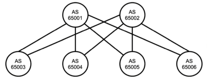
Referring to the exhibit, which two statements are true about BGP? Choose two.
A. The exhibit uses IBGP.
B. Devices should peer using loopback addresses.
C. The exhibit uses EBGP.
D. Devices should peer using physically connected IP addresses.
Explanation:
The exhibit shows six devices, each in a different AS:
AS 65001, 65002, 65003, 65004, 65005, and 65006.
Since each router belongs to a different Autonomous System (AS) , any BGP session between them must be External BGP (EBGP) , not IBGP.
Why C is correct:
EBGP is used for BGP peering between different AS numbers. The exhibit clearly shows each device in a distinct AS, so all peering relationships across these devices would be EBGP.
Why D is correct:
By default, EBGP peers assume they are directly connected (TTL=1). In a typical data center fabric or service provider edge, EBGP sessions are established using physically connected IP addresses (e.g., the IP address of the actual interface connecting the two routers). This avoids relying on an IGP or static routes to reach the peer’s peering address, and it follows the standard ebgp-multihop default of 1 hop.
Why the other options are incorrect (briefly):
A. The exhibit uses IBGP.
– Incorrect. IBGP requires all peers to be in the same AS. Here, each device has a different AS number, so IBGP is not applicable between them.
B. Devices should peer using loopback addresses.
– Incorrect. Using loopbacks for EBGP requires the ebgp-multihop command and a routing protocol or static routes to reach the loopback address. That is not the default behavior and is generally avoided unless necessary (e.g., for resiliency over multiple links). The default and typical method for directly connected EBGP peers is to use the physically connected interface IP addresses.
References:
Juniper TechLibrary – EBGP (External BGP)
"EBGP is used between routers in different autonomous systems. Peers are typically directly connected and use the interface IP addresses for peering."
JNCIA-DC Certification Guide, Domain 3 (Routing)
"EBGP peers normally use directly connected IP addresses for peering sessions. IBGP peers often use loopback addresses for resiliency."
You are troubleshooting a downed BGP session.
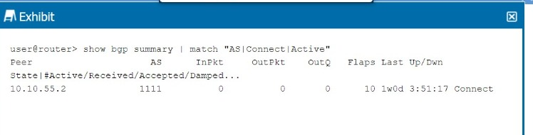
Referring to the exhibit, what is the cause of the problem?
A. The UDP session between the peers has not been established.
B. The local peer has sent an Open message but not received one from the remote peer.
C. The TCP session between the peers has not been established.
D. The local peer has sent an Update message but not received one from the remote peer.
Explanation:
The exhibit shows a BGP summary output with the peer 10.10.55.2 in the Connect state.
BGP states (in order) are:
Idle → Initial state.
Connect → BGP is waiting for the TCP connection to complete (or retrying).
Active → BGP is trying to initiate a TCP connection but fails repeatedly.
OpenSent → TCP established, Open message sent.
OpenConfirm → Open message received, waiting for Keepalive.
Established → Peering fully up.
Why C is correct:
The Connect state specifically indicates that BGP is actively trying to establish a TCP session (port 179) to the neighbor, but the TCP handshake has not yet completed. This could be due to:
Missing route to the neighbor’s peering address.
ACL/firewall blocking TCP port 179.
Neighbor not configured for BGP.
Interface down.
Why other options are incorrect (briefly):
A. The UDP session between the peers has not been established
. – Incorrect. BGP uses TCP (port 179), not UDP. UDP is used by other protocols like DNS, SNMP, or BFD, but not for BGP transport.
B. The local peer has sent an Open message but not received one from the remote peer.
– Incorrect. That scenario corresponds to the OpenSent state (TCP established, Open sent, awaiting Open reply). In Connect state, TCP is not yet up, so no Open message has been sent.
D. The local peer has sent an Update message but not received one from the remote peer.
– Incorrect. Update messages are exchanged only after the session reaches Established state. Connect state is much earlier in the BGP state machine.
References:
Juniper TechLibrary – BGP Finite State Machine
"In the Connect state, BGP is waiting for the TCP connection to complete. If the connection succeeds, an Open message is sent and the state moves to OpenSent. If it fails, the state may move to Active or back to Connect."
JNCIA-DC Certification Guide, Domain 3 (Routing)
"The Connect state indicates that BGP is attempting a TCP handshake with the neighbor. Failure to reach Established often points to missing routes, ACLs blocking TCP 179, or the neighbor not running BGP."
What is the purpose of generated routes? Choose one.
A. to create a route when required conditions are met
B. to create a unique routing table
C. to increase the number of route advertisements
D. to expand a single route advertisement into multiple routes
Explanation (~350 words):
A generated route in Junos OS is a logical route that is conditionally installed into the routing table only when specific contributing routes (also called "qualified routes") exist in the routing table. It is defined using the generate command under routing-options.
Why A is correct:
The primary purpose of a generated route is to create a route when certain predefined conditions are met —typically, when one or more contributing routes (with a specified prefix or tag) are present. The generated route does not have a direct next-hop but borrows the next-hop information from the contributing route. This is useful for summarizing routes or creating a default route that only becomes active when a specific internal route exists (e.g., for VPNs or conditional default routing).
Why other options are incorrect (briefly):
B. to create a unique routing table
– Incorrect. Generated routes exist within a routing table but do not create the table itself. Routing tables (e.g., inet.0, inet.3) are created by the system or by configuring routing instances.
C. to increase the number of route advertisements
– Incorrect. Generated routes often reduce the number of routes advertised by allowing route aggregation or conditional route generation. They are not designed to increase advertisement volume.
D. to expand a single route advertisement into multiple routes –
Incorrect. That describes route redistribution or policy-based route splitting, not generated routes. A generated route consumes contributing routes and produces one generated route, not multiple.
References:
Juniper TechLibrary – Generated Routes
"A generated route is installed in the routing table only when at least one contributing route is present. It inherits the next-hop from the contributing route."
JNCIA-DC Certification Guide, Domain 3 (Routing)
"Generated routes are conditionally created based on the existence of other routes in the routing table. They are useful for conditional defaults and selective route injection."
| Page 3 out of 9 Pages |