- 4.9/5.0
- 65 Questions
- Updated on: 3-Aug-2026
- Data Center Associate (JNCIA-DC)
- 165+ Prepared
- Valid Worldwide
Free JN0-281 Practice Test Questions | Know You're Ready for Data Center Associate (JNCIA-DC)
Which BGP attribute is used to prevent routing loops in a network?
A. MED
B. LOCAL_PREF
C. NEXT_HOP
D. AS_PATH
Explanation:
The AS_PATH attribute is BGP's standard loop‑prevention mechanism. When a BGP router receives an update, it examines the AS_PATH sequence. If the router finds its own AS number already listed, it immediately discards the route. This rejection occurs because the route has already exited that AS and is trying to re‑enter, which would create a routing loop. Without AS_PATH loop detection, BGP routes could cycle indefinitely between ASes.
Why other options are incorrect (briefly):
A. MED (Multi‑Exit Discriminator)
– Used by an AS to suggest a preferred entry path to neighboring ASes. It influences inbound traffic selection but has no loop‑detection capability.
B. LOCAL_PREF
– Used only within an AS to select the best outbound route to a destination. It is not exchanged between eBGP peers, so it cannot prevent loops across different ASes.
C. NEXT_HOP
– Specifies the next‑hop IP address to forward traffic toward a destination. Incorrect NEXT_HOP can break reachability, but it does not perform any loop‑checking function.
Additional context for the exam:
In a data center fabric running EBGP as the underlay (common in IP fabrics / Clos designs), AS_PATH loop prevention ensures that routes do not circle back through spine or leaf devices. For iBGP within the same AS, loop prevention is handled by split‑horizon rules (not AS_PATH), making AS_PATH specifically critical for eBGP scenarios.
References
Juniper TechLibrary – BGP Loop Detection
"If a BGP device receives a route that contains its own AS number in the AS_PATH, it rejects the route as a loop."
RFC 4271, Section 9.1.2 (BGP-4)
"If the AS_PATH attribute of a BGP route contains the local AS number, the route MUST NOT be considered further.
What are two names used to refer to the Layer 2 table that maintains known switching information? Choose two.
A. inet.0 table
B. routing information base RIB
C. Ethernet switching table
D. forwarding information base FIB
D. forwarding information base FIB
Explanation:
The Layer 2 table that maintains known switching information (MAC addresses, associated VLANs, and egress interfaces) is referred to by two common names in Juniper networks and industry standards.
C. Ethernet switching table
– This is the descriptive, platform-neutral name for the table. It stores MAC address to port mappings. When a switch receives a frame, it looks up the destination MAC in this table to determine where to forward the frame (unicast, flood, or discard).
D. forwarding information base (FIB)
– In Junos OS, the FIB is the actual hardware-forwarding table used by the Packet Forwarding Engine (PFE). For Layer 2 switching, the FIB contains the learned MAC addresses and their associated interfaces. While many associate FIB with Layer 3 routing, in a switching context, the Layer 2 FIB is the operational table that drives frame forwarding decisions.
Why the other options are incorrect (briefly):
A. inet.0 table
– This is a Junos routing table for IPv4 unicast routes (Layer 3). It stores IP prefixes and next-hop information, not MAC addresses or switching information.
B. routing information base (RIB)
– The RIB is a control-plane table (e.g., inet.0, inet6.0) that stores routing information learned from routing protocols or static configuration. The RIB is not a Layer 2 switching table; it feeds into the FIB but does not itself maintain MAC forwarding entries.
References:
Juniper TechLibrary – Layer 2 Forwarding
"The Ethernet switching table (also known as the MAC address table or Layer 2 FIB) contains MAC addresses and their associated VLAN and interface information."
JNCIA-DC Certification Guide, Domain 2 (Data Center Switching)
"The forwarding information base (FIB) for Layer 2 is the MAC forwarding table, also called the Ethernet switching table."
Which feature should be used with a static route that has a secondary next hop with a unique route preference value? Choose one.
A. retain
B. resolve
C. qualified next hop
D. install
Explanation:
In Junos OS, when you need to configure a static route that has a secondary next hop with a unique route preference value, you use the qualified next-hop feature.
The qualified next-hop statement allows you to associate different preference (administrative distance) values with different next-hop addresses for the same destination prefix. The primary next hop uses the default static route preference (typically 5 for IPv4 or 10 for IPv6, depending on Junos version), while each qualified next hop can have its own preference value. The route with the lowest preference value is installed into the forwarding table.
This is commonly used for floating static routes (backup routes). For example, you can configure an Ethernet link as the primary path with preference 5, and a secondary path (e.g., a slower backup link) as a qualified next hop with preference 12. The backup route only becomes active when the primary route fails.
Why other options are incorrect (briefly):
A. retain
– This option keeps a static route in the routing table even if the next hop becomes unreachable. It does not allow per-next-hop preference configuration.
B. resolve
– This allows a static route's next hop to be indirectly resolved through another route in the routing table. It does not provide secondary next hops with unique preferences.
D. install
– This forces a static route into the forwarding table even if its preference is not the best. It does not enable multiple next hops with different preference values.
References:
Juniper TechLibrary – Qualified Next Hops for Static Routes
"You can specify a preference value for each qualified next hop, which allows you to control which next hop is selected as active."
JNCIA-DC Certification Guide, Domain 3 (Routing)
"Qualified next hops allow a static route to have multiple secondary paths, each with its own preference. This provides granular control over route failover."
Which statement is correct about building an IP fabric?
A. Each spine device should have a direct physical connection to every other spine device.
B. Each spine device should have a direct physical connection to every leaf device.
C. Each spine device must have two or more physical connections to each leaf device.
D. Each spine device must have two or more physical connections to every other spine device.
Explanation:
In a standard IP fabric (also known as a Clos or spine‑leaf architecture) used in modern data centers, the design follows a simple, non‑blocking topology:
Spine layer – Acts as the aggregation/core, providing high‑speed interconnectivity.
Leaf layer – Connects to servers, storage, or network services.
The fundamental rule is: Every spine device connects to every leaf device, and no direct spine‑to‑spine or leaf‑to‑leaf connections are required (though leaf‑to‑leaf may exist via the spine). This creates a full bipartite mesh between the two layers. Each spine sees all leaves, and each leaf sees all spines.
Why B is correct:
Each spine device must have a direct physical link to every leaf device to ensure that any leaf can reach any other leaf through at most two hops (leaf → spine → leaf). This provides predictable latency, easy scaling (add spines or leaves independently), and ECMP (Equal‑Cost Multi‑Path) benefits.
Why other options are incorrect (briefly):
A. Each spine device should have a direct physical connection to every other spine device.
– Incorrect. Spine‑spine connections are not part of a standard IP fabric. They would create a traditional multi‑tier core, not a Clos fabric, and can introduce unnecessary complexity and forwarding loops.
C. Each spine device must have two or more physical connections to each leaf device.
– Incorrect. While redundancy is good practice (e.g., two links from a leaf to each spine for bandwidth and resilience), it is not a requirement of the IP fabric definition. The fabric only requires at least one connection per spine‑leaf pair.
D. Each spine device must have two or more physical connections to every other spine device.
– Incorrect. Spine‑spine links are not part of the IP fabric model and are unnecessary. Adding them would break the fabric’s simplicity and ECMP symmetry.
References:
Juniper TechLibrary – IP Fabric Underlay
"In a spine‑leaf IP fabric, each spine device is connected to every leaf device. No spine‑to‑spine or leaf‑to‑leaf links are required."
JNCIA-DC Certification Guide, Domain 4 (Data Center Fabrics)
"A Clos IP fabric requires full‑mesh connectivity between the spine and leaf layers. Adding spines increases capacity and redundancy without affecting existing leaves."
A switch receives an Ethernet frame that contains source and destination MAC addresses that are not in the Ethernet switching table. In this scenario, which two actions does the switch perform? Choose two.
A. The switch floods the frame out every port in the broadcast domain except the ingress port.
B. The switch adds the source MAC address to the Ethernet switching table.
C. The switch drops the frame.
D. The switch forwards the frame to the Routing Engine.
B. The switch adds the source MAC address to the Ethernet switching table.
Explanation:
When a switch receives an Ethernet frame and neither the source MAC nor the destination MAC is found in the Ethernet switching table (MAC address table / Layer 2 FIB), the switch performs two specific actions:
A. Flood the frame
– Because the destination MAC is unknown, the switch does not know which port to forward the frame to. By default, it floods (broadcasts) the frame out all ports that belong to the same VLAN (broadcast domain), excluding the ingress port where the frame was received. This ensures the frame reaches the intended device, which will eventually respond and allow the switch to learn its MAC address.
B. Add the source MAC to the table
– The switch learns the source MAC address from the incoming frame. It records the source MAC, the VLAN, and the ingress interface into the Ethernet switching table. This entry is then used for future forwarding decisions to that specific MAC address.
Why the other options are incorrect (briefly):
C. The switch drops the frame.
– Incorrect. A switch only drops a frame under specific conditions (e.g., STP blocking, ACL deny, MTU exceed, or frame errors). An unknown unicast frame is flooded, not dropped. Dropping would cause connectivity failures in normal operation.
D. The switch forwards the frame to the Routing Engine.
– Incorrect. In normal switching, frames are processed by the Packet Forwarding Engine (PFE) in hardware. Only frames destined for the switch's own MAC (e.g., management traffic, BPDUs, control protocols) or exception traffic are sent to the Routing Engine (RE). Unknown unicast flooding does not go to the RE unless specifically configured (e.g., mirroring).
References:
Juniper TechLibrary – Ethernet Switching MAC Learning
"When a switch receives a frame with a source MAC address not in its MAC table, it adds that address and the associated VLAN and interface. If the destination MAC is unknown, the frame is flooded out all ports in the VLAN (except the incoming port)."
JNCIA-DC Certification Guide, Domain 2 (Data Center Switching)
"Unknown unicast flooding and source MAC learning are the two immediate actions when a frame arrives with both MAC addresses absent from the switching table."
You are asked to ensure that traffic and routing information is not interrupted if your primary Routing Engine fails or switches to the backup Routing Engine. In this scenario, which high availability feature will accomplish this behavior?
A. nonstop active routing NSR
B. graceful Routing Engine switchover GRES
C. link aggregation control protocol LACP
D. bidirectional forwarding detection BFD
Explanation:
When you need to ensure that both traffic forwarding and routing information are not interrupted during a failover from the primary Routing Engine (RE) to the backup RE, you require Nonstop Active Routing (NSR).
Why other options are incorrect (briefly):
B. graceful Routing Engine switchover (GRES)
– Ensures forwarding continues uninterrupted during RE switchover by synchronizing the FIB, but routing protocols restart because protocol state is not preserved. Neighbors see adjacency loss unless combined with NSR or graceful restart.
C. link aggregation control protocol (LACP)
– Provides link redundancy and load-balancing at Layer 2, but does nothing to preserve routing information or RE failover behavior.
D. bidirectional forwarding detection (BFD)
– Provides fast failure detection between routers, but does not preserve routing information during an RE switchover. BFD sessions would fail without NSR.
References:
Juniper TechLibrary – Nonstop Active Routing (NSR)
"NSR preserves routing protocol state during RE switchover, ensuring that peer routers detect no control plane disruption. Both forwarding and routing information remain intact."
JNCIA-DC Certification Guide, Domain 5 (High Availability)
"NSR synchronizes the routing protocol state to the backup RE. When a failover occurs, the backup RE continues routing adjacencies without interruption. GRES alone only preserves forwarding (FIB)."
Referring to the exhibit, which type of protocol session will be established?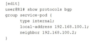
A. OSPF
B. IS-IS
C. EBGP
D. IBGP
Explanation
The exhibit shows a BGP configuration snippet:
text
group service-pod {
type internal;
local-address 192.168.100.1;
neighbor 192.168.100.2;
}
The keyword type internal; explicitly configures this BGP group as an internal BGP (IBGP) session. In Junos, type internal means the peer belongs to the same Autonomous System (AS). The local‑address and neighbor address (both in 192.168.100.0/24) are used for the TCP session, but the critical differentiator is the internal type.
Why D is correct:
type internal tells Junos that the neighbor 192.168.100.2 is in the same AS as the local router. Therefore, the session established will be IBGP.
Why other options are incorrect (briefly):
A. OSPF – The configuration explicitly shows protocols bgp. There is no OSPF configuration present.
B. IS-IS – Not configured. The snippet is under protocols bgp, not protocols isis.
C. EBGP – EBGP requires type external; or no explicit type with different AS numbers configured via peer-as. The type internal explicitly prevents EBGP.
References:
Juniper TechLibrary – BGP Groups (Internal vs. External)
"When you configure a BGP group with type internal, all peers in that group are IBGP peers and must belong to the same AS."
JNCIA-DC Certification Guide, Domain 3 (Routing)
"IBGP sessions are defined by the 'type internal' statement in the BGP configuration. EBGP uses 'type external' or the 'peer-as' statement with a different AS number."
In a three-stage IP fabric, what is the sequence of fabric node stages that a packet passes through?
A. leaf to spine to spine to leaf
B. spine to leaf to spine
C. leaf to spine to leaf
D. superspine to spine to leaf
Explanation:
A three-stage IP fabric (also known as a three-stage Clos network) consists of three layers:
Leaf layer – Connects to servers and end devices.
Spine layer – Acts as the middle stage, interconnecting all leaf devices.
There is no third switching layer beyond leaf and spine in a basic three‑stage fabric; the "three stages" refer to ingress leaf → spine → egress leaf.
Why C is correct:
This matches the fundamental three‑stage Clos topology where any leaf‑to‑leaf communication goes through exactly one spine device. The spine provides full‑mesh connectivity between leaves without any direct leaf‑to‑leaf or spine‑to‑spine links.
Why other options are incorrect (briefly):
A. leaf to spine to spine to leaf
– This would be a four‑stage fabric (leaf → spine → spine → leaf), which is not a three‑stage IP fabric. Standard three‑stage fabrics do not have spine‑to‑spine hops.
B. spine to leaf to spine
– Incorrect because traffic does not originate at a spine. Spines are intermediate nodes; servers connect only to leaves.
D. superspine to spine to leaf – This describes a five‑stage or spine‑superspine architecture (e.g., folded Clos with a superspine layer). A basic three‑stage fabric has no superspine.
References:
Juniper TechLibrary – IP Fabric Architecture (Clos)
"In a three‑stage Clos fabric, a packet traverses from an ingress leaf to a spine and then to an egress leaf. There are no spine‑to‑spine links."
JNCIA-DC Certification Guide, Domain 4 (Data Center Fabrics)
"Three‑stage Clos = leaf + spine. Forwarding path is leaf → spine → leaf. Spine‑to‑spine paths do not exist."
| Page 2 out of 9 Pages |